Given Blue Opal’s data network is linked to a ShipModul that beacons the data on a wireless network, I felt like it would be kind of neat to build my own data logger that can log all the data that the ShipModul is broadcasting. As mentioned in another post, I currently use iNavX on an iPad Mini for my recording process, but I’ve found that it’s not very good at it (I sent them feedback on how they could make it much better in my view).
Given this is a boat, I want a logger that consumes minimal power, writes to an SD card, and has some intelligence about how it writes things like GPS data – iNavX puts ALL of the points ever recorded in a single list; I’d like it to at least group tracks by day to make exporting easier. There are commercial products that are designed to tap a NMEA bus, but I felt this would be a good chance to play with a micro-controller.
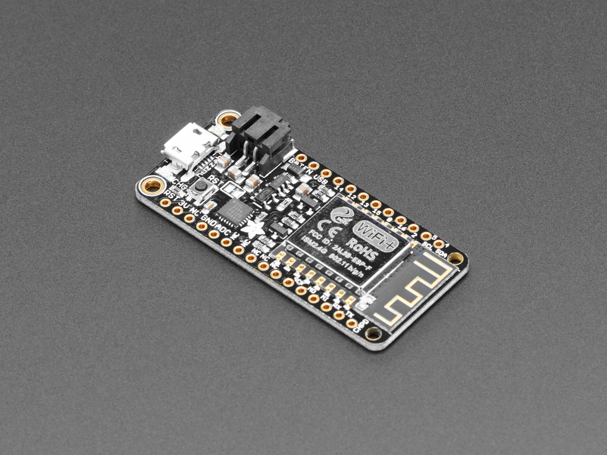
Enter the ESP8266 microcontroller. My particular one comes from Adafruit in the USA, a Feather HUZZAH to be precise. The specs are decent, and include a battery charging circuit, which means I can always make it portable if I feel so inclined – if it’s on Blue Opal, it’ll be connected to the house batteries. I could have used a Raspberry Pi for this, perhaps a Zero W model, but a Raspberry Pi typically needs several hundred mA of current to run; in contrast, the ESP8266 board runs in the microamp territory. I’ve been replacing as many of the power drains as I can, so it didn’t really make sense to put a Pi into service here, even if it’s a device I’m more familiar with (since it’s just a Linux computer).
The downside to the ESP8266 board is that it doesn’t have any kind of display (though neither does a Pi), nor any integrated storage beyond the 4 MB of flash space. Flash effectively degrades every time you write to it, so using the on-board flash for storing the NMEA logs is a no-go. Adafruit also provide a 2.4″ touchscreen TFT “wing” for the Feather, which features an integrated MicroSD card slot, so I figured this would let me experiment with writing code that could display information on the TFT, while using a SD card as the storage location for the logs. This increases the power draw of the unit, though I’m having trouble finding the full current draw specifications – I at least know that the backlight of the TFT will draw about 60 mA.
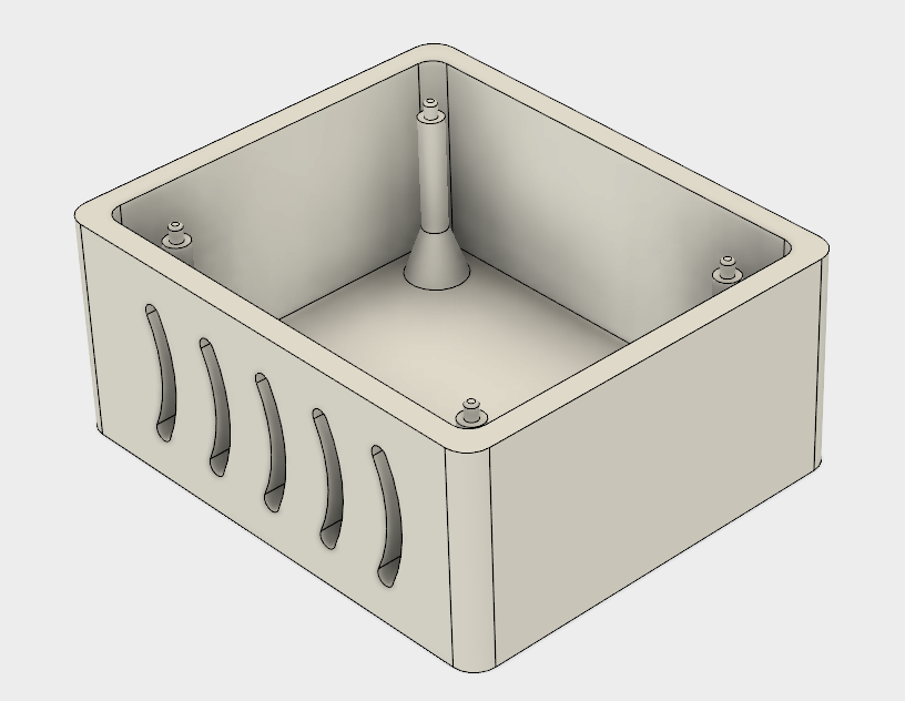
In a classic case of putting the cart before the horse, I’ve also mucked around in Fusion 360 and generated a starting sketch and 3D model for a case to hold the Feather and Featherwing assembly (there’s nothing on Thingiverse). Still need to add cut-outs to provide access to the SD card, power socket, and reset button, but as a prototype to run off on the 3D printer at work, it’ll do. Also needs a lid that’s modeled around the TFT specifications, so that the unit is as enclosed a possible; I probably don’t need the ventilation grille on a 80 MHz CPU microcontroller, but it was good practice in Fusion. Plus, I’d like to see if the printer at work can deal with the overhangs that the grille produces – it should, because there’s a lot of support below each level that it has to print.
So, that’s the backstory.
First test was to load up the Arduino IDE and see if the board, as-shipped, worked. This involved adding a URL to the preferences to state where the IDE could find the board specifications, adding the board via the Boards Manager, and then loading some Adafruit libraries via the Library Manager. The sample code then promptly failed to work, but not because the board is broken. I had installed the IDE from the Windows store, and apparently that install doesn’t come with the USB FTDI drivers that are required to actually talk to the board. A quick re-install from the full installation package got me the drivers, and the TFT started displaying the graphical demo version of “Hello World”. Success!
Now I’m on to getting the board to run MicroPython instead. I’m comfortable in Python, so for the first go round it’ll be my language of choice (and this influenced my choice of board). Getting MicroPython loaded on is easy enough – install Python3 for Windows, start a PowerShell, pip install esptool, and then some CLI incantations to load the latest MicroPython firmware on to the board. WebREP refused to work, but a serial connection at 115200 worked just fine.
The TFT display needs some .mpy files from Github, but when I connect to the REPL over the serial port, I get a lovely error message about how they’ve been built for the wrong version of MicroPython (ili9341 and rgb both). Now I’m at the stage of trying to build some cross-compiled frozen bytecode editions of the original files from Adafruit’s Github, because why should this be easy? The process starts by following some Adafruit documentation (which is old, and they state it’s old), which leads to errors when trying to build the cross compiler package. Nuked all of the packages that the Vagrant recipe had downloaded, and started with an up to date download of the ESP Open SDK – this has built happily.
Next up, with the SDK built and my PATH environment set to reference it, build the cross compiler for MicroPython; just a matter of make -C mpy-cross after downloading the MicroPython source code. With that done, a quick git clone of the Adafruit repository, and then invoke mpy-cross against the two .py files I need. Copy them over to /vagrant so that I can see them in Windows, and chuck them across the USB-serial connection…
Load up the serial console via PuTTY, open a browser to Adafruit’s ILI9341 documentation, and we have code that happily talks to the SPI-driven display!
All that’s left now is capturing some NMEA traffic from the ShipModul so I can replay it on my home network, use the PyNMEA library to decode it, work out how to talk to the SD card, and log it all. Then, perhaps I’ll write it in the Arduino IDE instead to learn something new.