Blue Opal’s battery layout, like everything on a boat, made compromises. In the port side of the saloon, there’s a small locker under the aft central cushion, and a long locker under the aft port cushion. The two house batteries occupied the entire small locker, running transverse across the hull, and the port locker had a single starter battery running fore-aft, situated aft in the locker.

I wanted to add some monitoring capabilities for my batteries – nothing complex, just a dual voltmeter and 100A ammeter – and there really wasn’t a nice place to put them. The chart table is full of navigation gear, and the wiring locker behind the chart table was kind of full of wires, and I was loath to add more wiring in there if I could avoid it.
The formulated plan was to build an extended battery platform in the port locker, and accept the fact that I was moving another battery outboard (which affects trim, though on a 9 ton yacht, I’m not sure a single battery matters compared to my mass), and sacrificing the entire port locker to batteries, fuses, and cabling. House batteries would move to the port locker, and the starter battery would occupy the former house battery locker, with more room for fuses, wiring, monitoring gear etc.
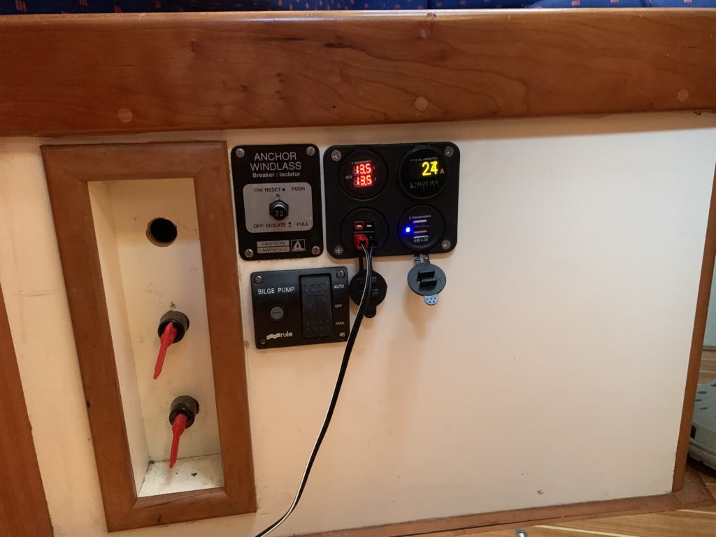
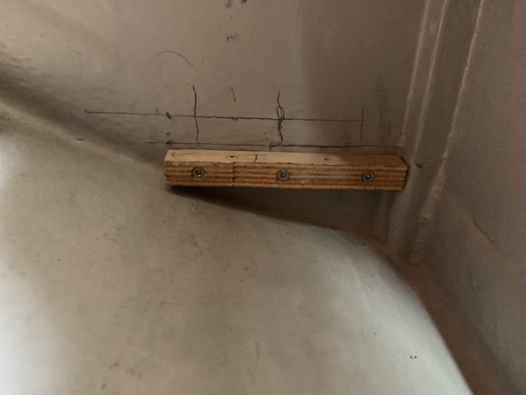
The first task was to get a 18mm marine plywood base installed. I cut the battens earlier in the week using the club jigsaw (which was a bit blunt, but worked), and got the first one installed by using a second batten as a depth template.
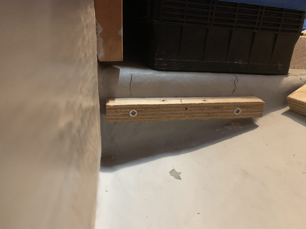
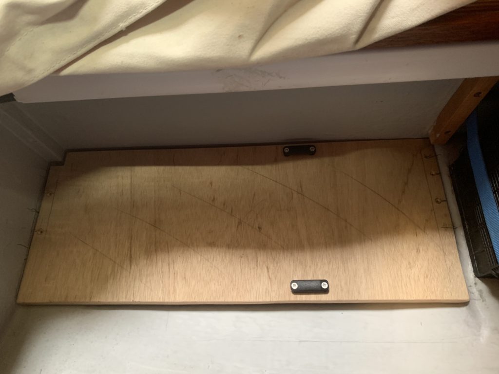
The second batten went in over the weekend, and then a bit of cardboard was used to form the template for the base itself. Given the state of the jigsaw, I resorted to using a Bosch 40-30 multi-cutter, and Dad held the wood very carefully. A quick round-over on the edges and corners to remove splinters, and in it went. Two footman loop mounts were used to fit a tie-down strap; held in with #8 screws. The board needs to be coated in epoxy to protect it, so I’ll have to take it all to pieces once I’ve moved in to my house and am not relying on the boat to be my home.
We didn’t put a batten at the back, and I’m not sure that one is needed. However, I’ll probably mark some lines and fit one just to provide a bit more support. Also need to seal the edge of the board against the hull, and I’ll probably do it with Sikaflex so that the board can be taken up in the future if needed.
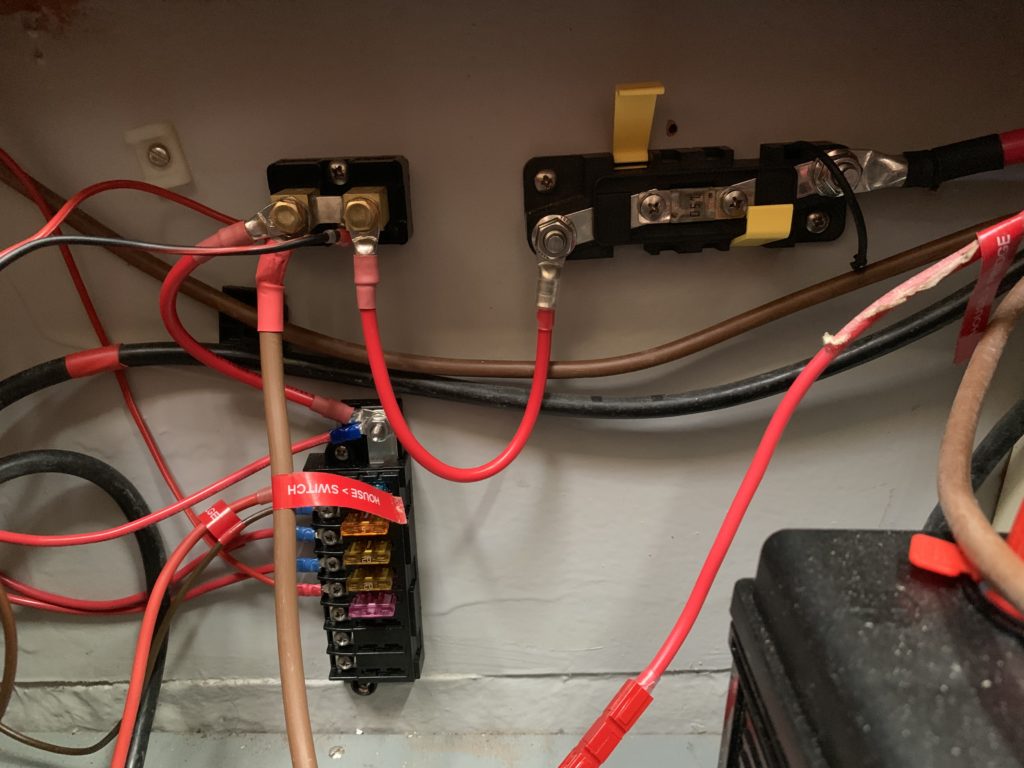
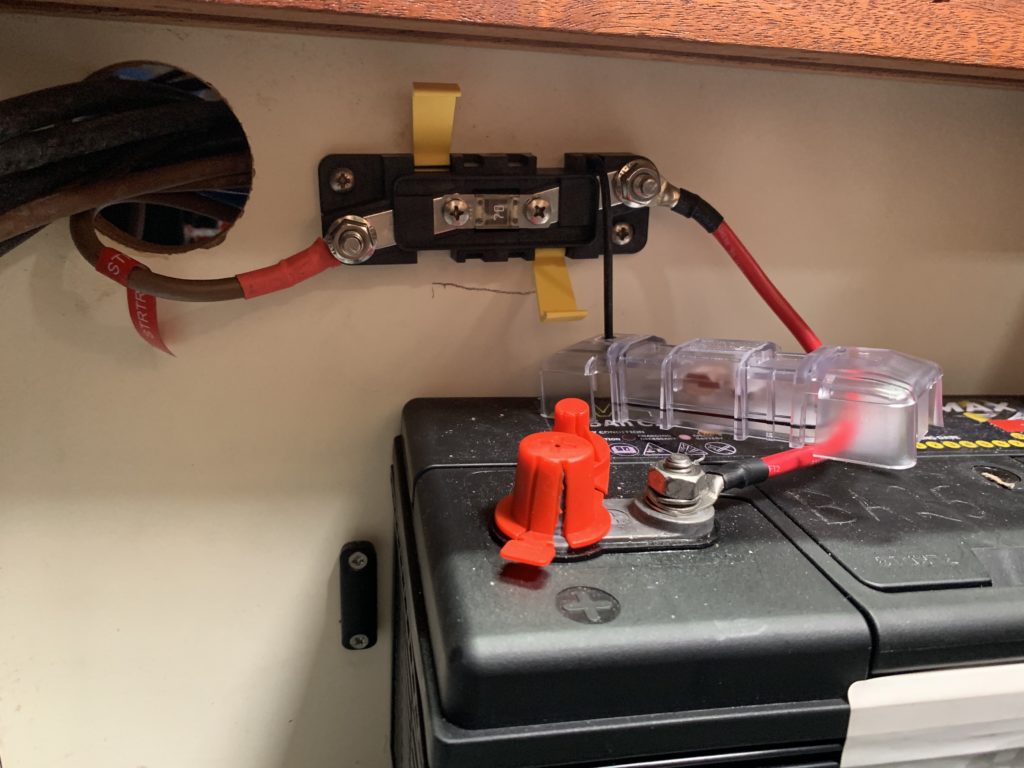
The rest of the work involved disconnecting all the cabling, taping the ends to avoid infinity-amp sparks and badness, and mounting various 70 and 150 amp MIDI fuses using BlueSea Systems equipment, as well as a small 8 terminal ATC fuse block to provide fused take-off for always-on circuits like the bilge pump, fridge, and saloon overhead light. The ammeter comes with big yellow numbers printed on the front of it, and no mention (that I could find) of how to get them off; don’t try and scrape them off, use a small bit of acetone on a piece of paper towel and they’ll come right off.
The wiring run from the house batteries goes house battery positive to 150 amp fuse to 100A shunt. From the shunt, two feeds come off – one to the ATC fuse block, and the other to the live side of the main battery switch. The ammeter, dual voltmeter, USB socket, and PowerPole sockets all take power from the ATC fuse block, so they’re currently not turned on/off by the main house battery switch. Their draw is in the milliamps range, vs the 3+ amps that the fridge draws, so I can live with it for now.
The safety fuse holders helpfully hold the replacement MIDI fuse.
With the core wiring done, it was a relatively quick job to drill out the four holes for the ammeter etc. Well, once we went alongside on shore power and got the electric drill from the club (and put my portable drill on charge, both batteries needed a good charge). A small circular bit, drill until the centre drill breaks through the 3/4″ ply, and then drill from the back to eliminate tearout around the socket holes.
The Sterling charger is connected to the live side of the battery switches, so the charging current from it flows through the shunt and 150 amp fuse on the house side (the starter battery side probably needs a bit of a rejig). This also means I can see the charging amps on shore power, which is neat, though not essential. The ProSplit R feeds the batteries via 70 amp MIDI fuses, and is upstream of the shunt, so that charging current is not visible on the ammeter.
A very useful thing for this rewiring was a Draper battery terminal crimping tool. Insert wire into lug. Insert lug into the V of the crimper, flat part up. Have someone hold the wire and crimper carefully. Whack it hard with a hammer. Do it right, and that lug will be on nice and tight.
We didn’t install the BS6006 switch to inline the house batteries on the engine battery (for when you really need to crank the engine, and the starter is dead), because I don’t know how it’ll interact with the ProSplit R. Need to send an email enquiry. Also need to do some cable tidying in the small locker; probably cable ties, maybe velcro.
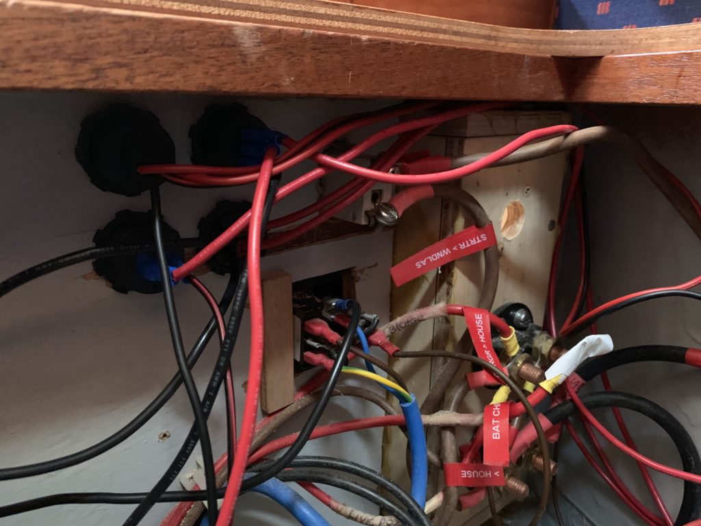
Next up, re-wiring the wiring locker behind the chart table.
Oh, and I need to find my red/black Dymo label reels and add more labels to this setup.
