I went up to the yard yesterday afternoon at the same time K went to the airport. The goal for the visit was fairly simple – run the calibration and setup of the autohelm system so I could be absolutely sure that it all worked, before the yard does the sound insulation installation and puts the engine back in. Last Sunday proved that power was in place, and that the p70s could see the ACU and EV-1, but I’d not actually had time to verify that the ACU would control the rudder. Secondary goals included getting the hole at the chart table enlarged for the new i70s, and hooking up the ITC-5 transducer converter.
The autohelm setup was a doddle – connect the p70s via a spur to the backbone at the helm, verify the rudder was centered (went down to the ground and eyeballed it), apply power, follow instructions for dockside setup. What was not a doddle, however, was the fact that I could get 30 degrees of port rudder and only 24 degrees of starboard rudder.
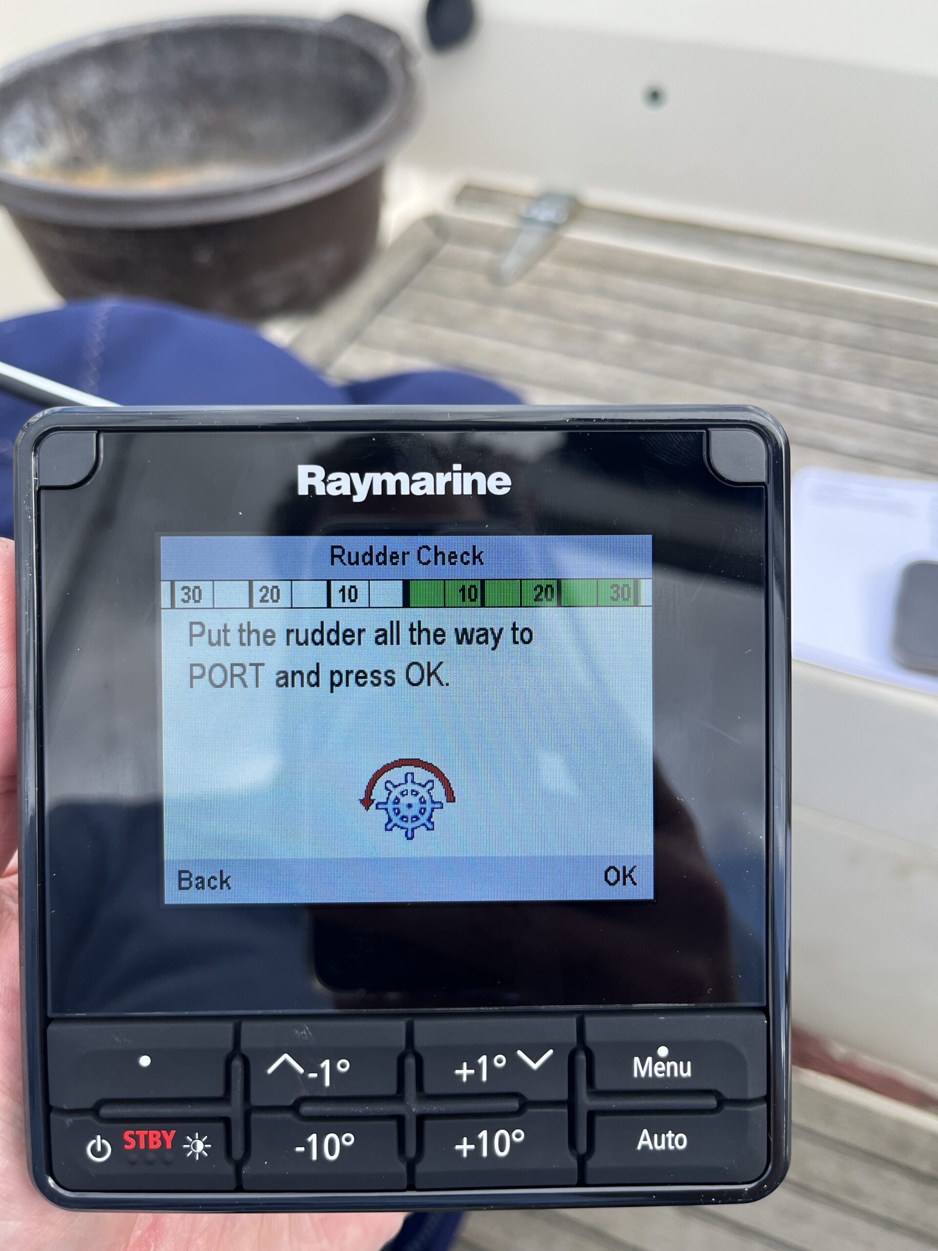
Now, I’ve noticed this before, but not in those terms. The helm has always had resistance when put hard over to starboard, and K has noticed this as well. I’ve never thought much of it, until I realised yesterday that without the linear drive connected, I don’t feel the resistance. Since the issue has shown up with two different drives connected, I put the helm hard over to starboard and went below to look at the drive ram. Sure enough, it’s at the stops, fully retracted, and the rudder hasn’t been turned the complete distance.
The yard hasn’t done the insulation work yet, so I pottered over to the yard office and had a chat with Gregor (yard manager). A bit of sucking of teeth when I asked whether they could fix the mounting position any time soon, but then agreement that since they were doing the sound insulation today, they could fit the removal, move, drill, bolting back work in. So I’ll hopefully find out by this weekend if they’ve fixed it.
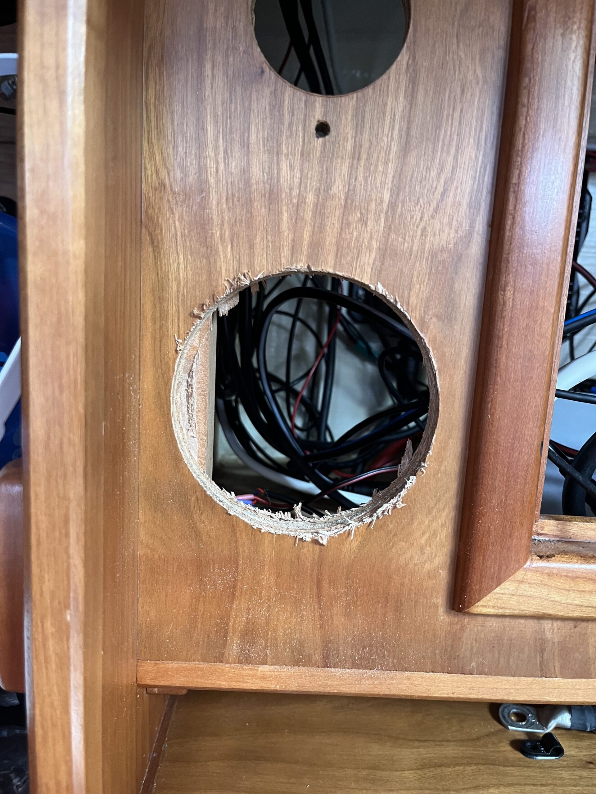
With that sorted, I started working forwards to close up works and tidy up. I skipped past the ACU work, and decided to focus on getting the chart table i70s installed. Before applying the 92mm hole saw (and my $deity that thing has a kick on a cordless drill), I looked carefully at the location to make sure there were no cables that would get snagged by the cutter as it broke through to the inside of the wiring locker. This is when I noticed that there’s a vertical batten in the corner.
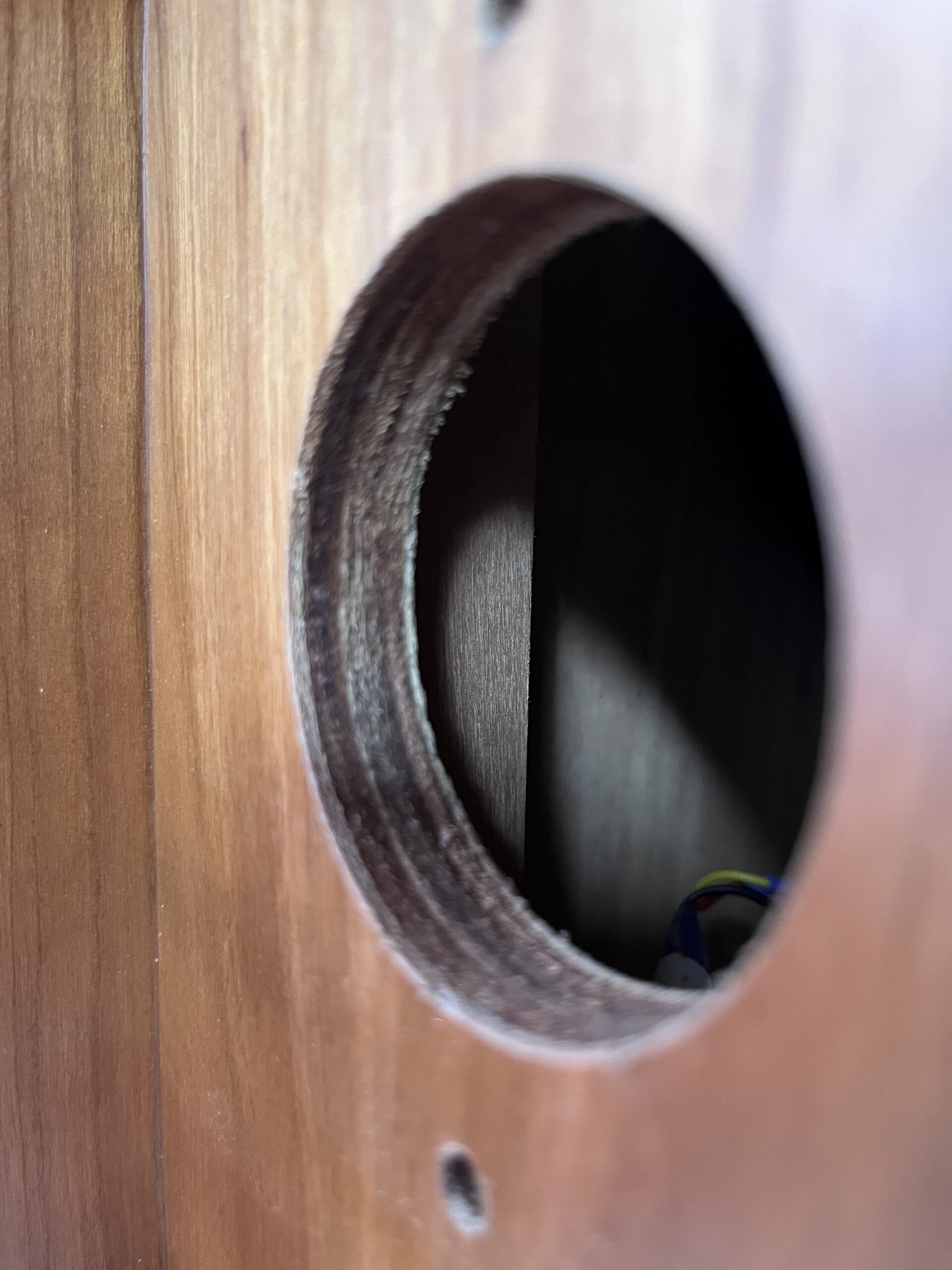
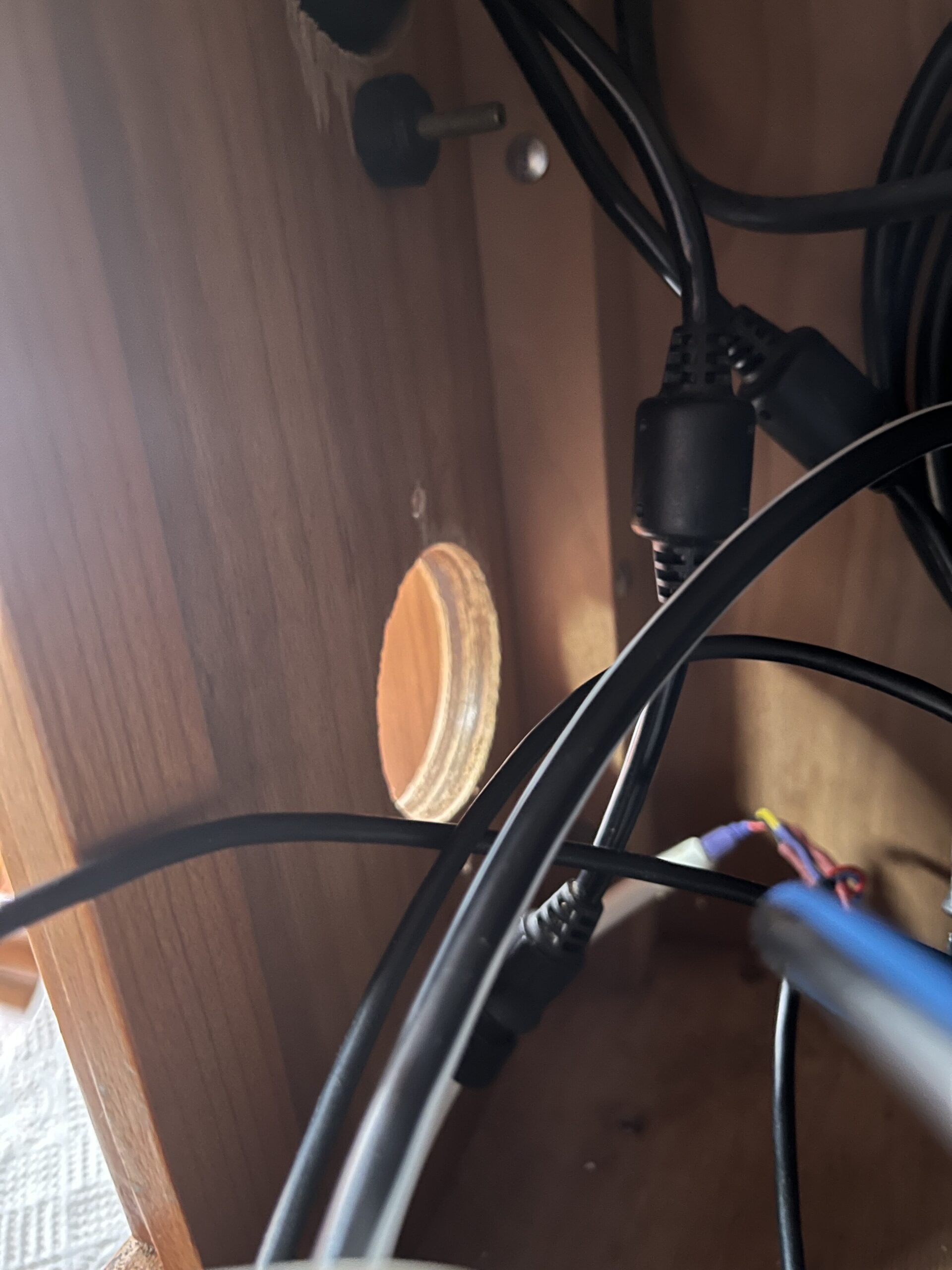
I mentally shrugged, and figured I’d work out how to deal with that bit once I’d got the hole cut. The one worry was the screw that’s visible right in line with the existing 51mm hole. Turned out to not be a problem, at least for the hole saw work.
I had contemplated various ways to get the plug I’d cut (as a guide for the drill bit) mounted in the hole, near enough to dead centre to not matter. These included
- fixing the plug to a backing plate, getting it in the right place, screwing through the face of the locker into the backing plate (the existing machine screw holes are at 70mm, could have used those)
- PU glue – the one that expands when exposed to moisture, though it takes an hour to set, and would be fiddly to hold everything in place
- thickened epoxy – basically the same approach as PU glue
- hot glue – same approach, but it cures/chills in minutes
The hot glue thing is something I’ve seen wood turners use to hold blanks on a lathe. I figured if it’ll hold a few kg of wood spinning at hundreds of RPM, it should hold the plug in place to act as a bearing/guide for a drill bit – the hole was already drilled after all.
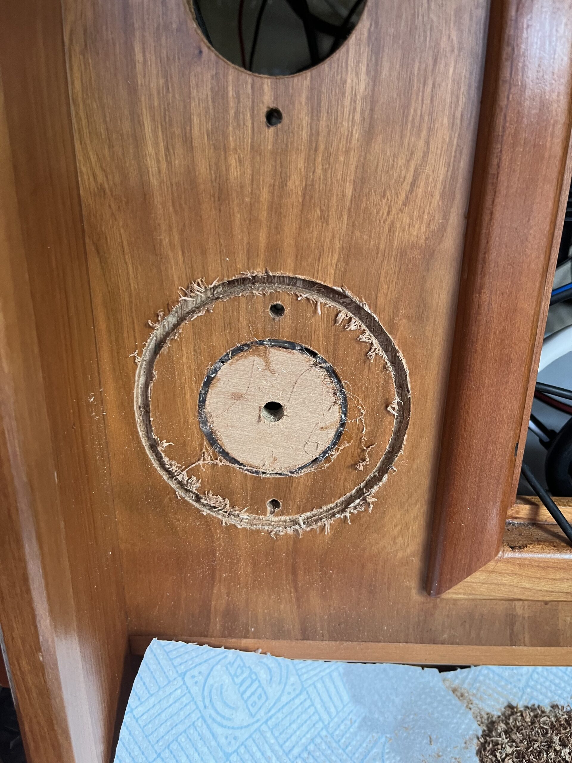
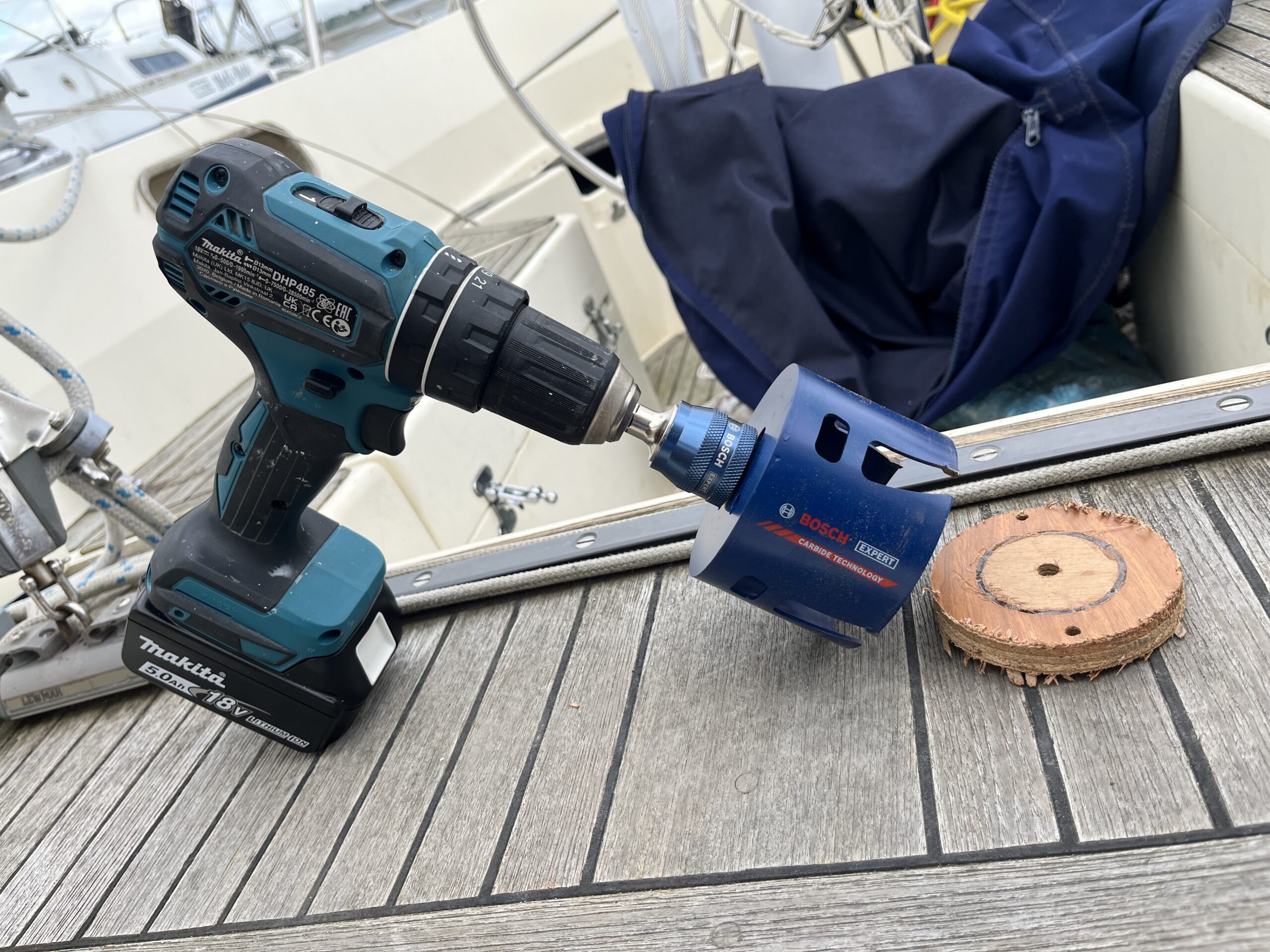
It’s not the neatest of cuts, being veneered plywood, but nothing a quick sanding/filing couldn’t sort out. As noted earlier, that 92mm cutter has a hell of a kick on a brushless 18V drill, and that was in low gear. The cutter indicates something like 400 RPM for wood, and low gear caps at 500 RPM. The hot glue worked so well I couldn’t get the plug back out; tried cutting it out for a few minutes in case I wanted to re-use it, then shrugged and chucked it – I have more plywood.
I tried to fit the new display unit, and found that it’s just that little bit thicker than the plywood, so the vertical batten is indeed a problem. My first thought was to make a spacer plate, but that’d take more time than I want to spend on this. My second thought was that a drill bit, carefully handled, will act like a spinning chisel.
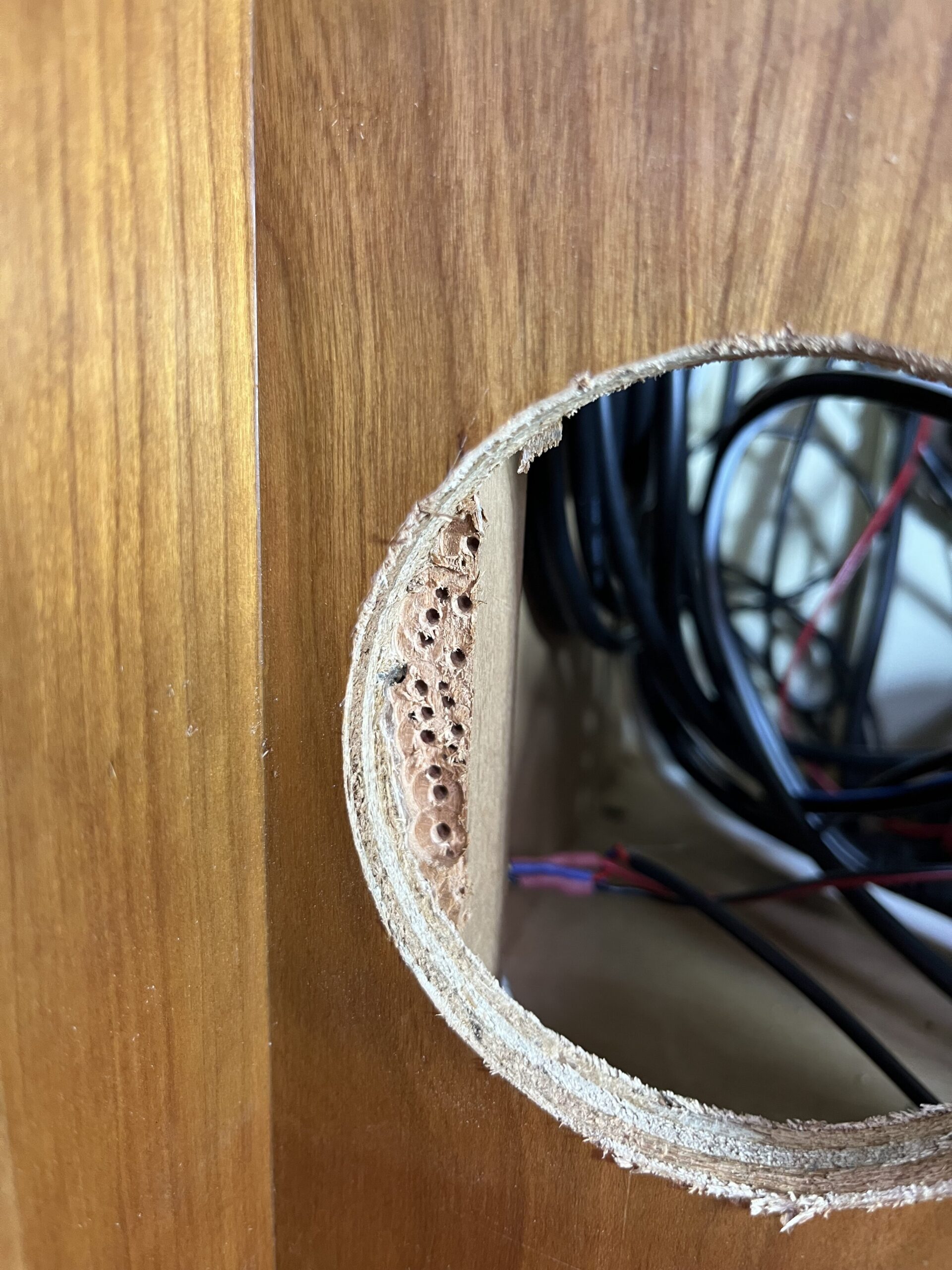
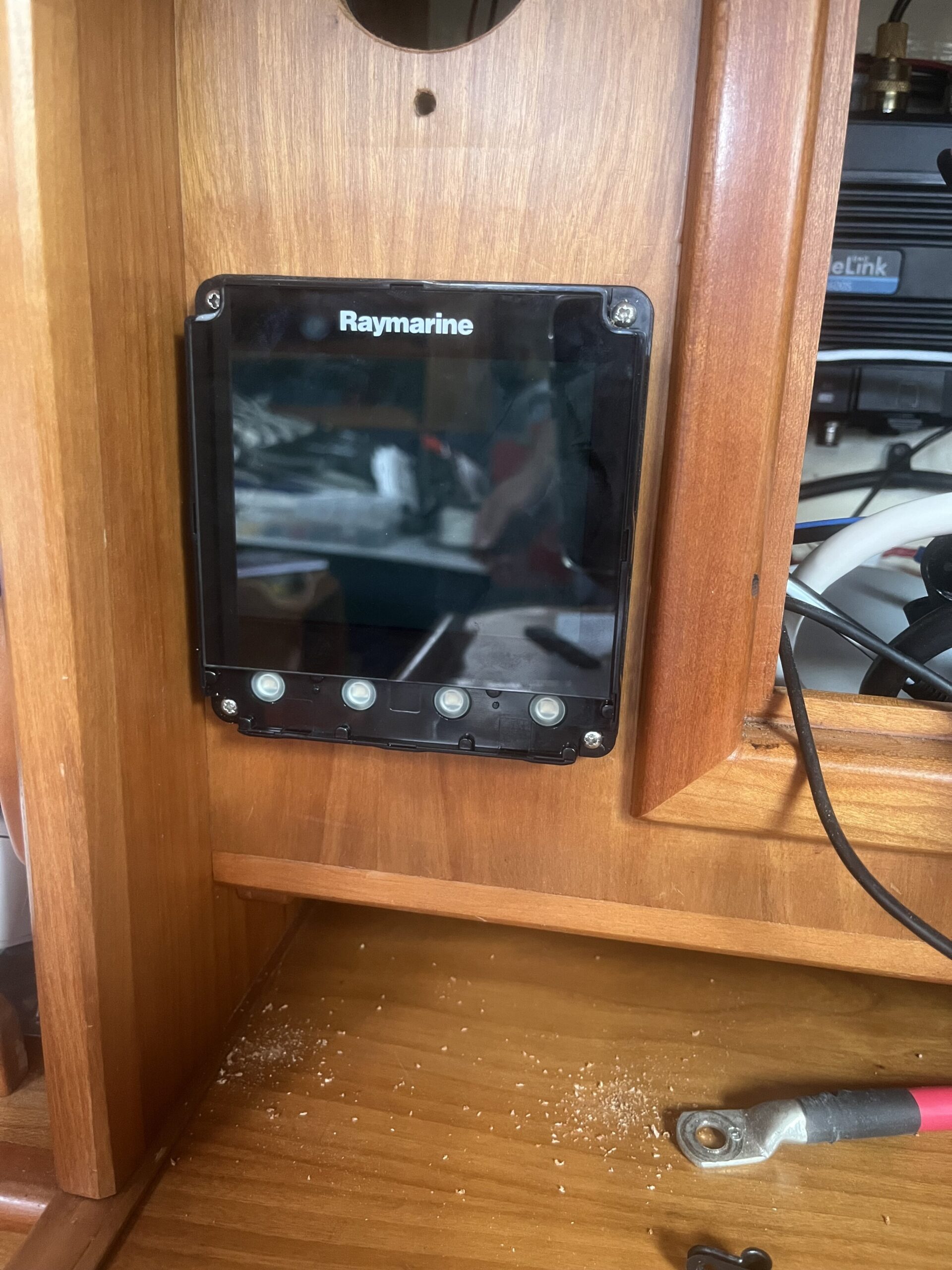
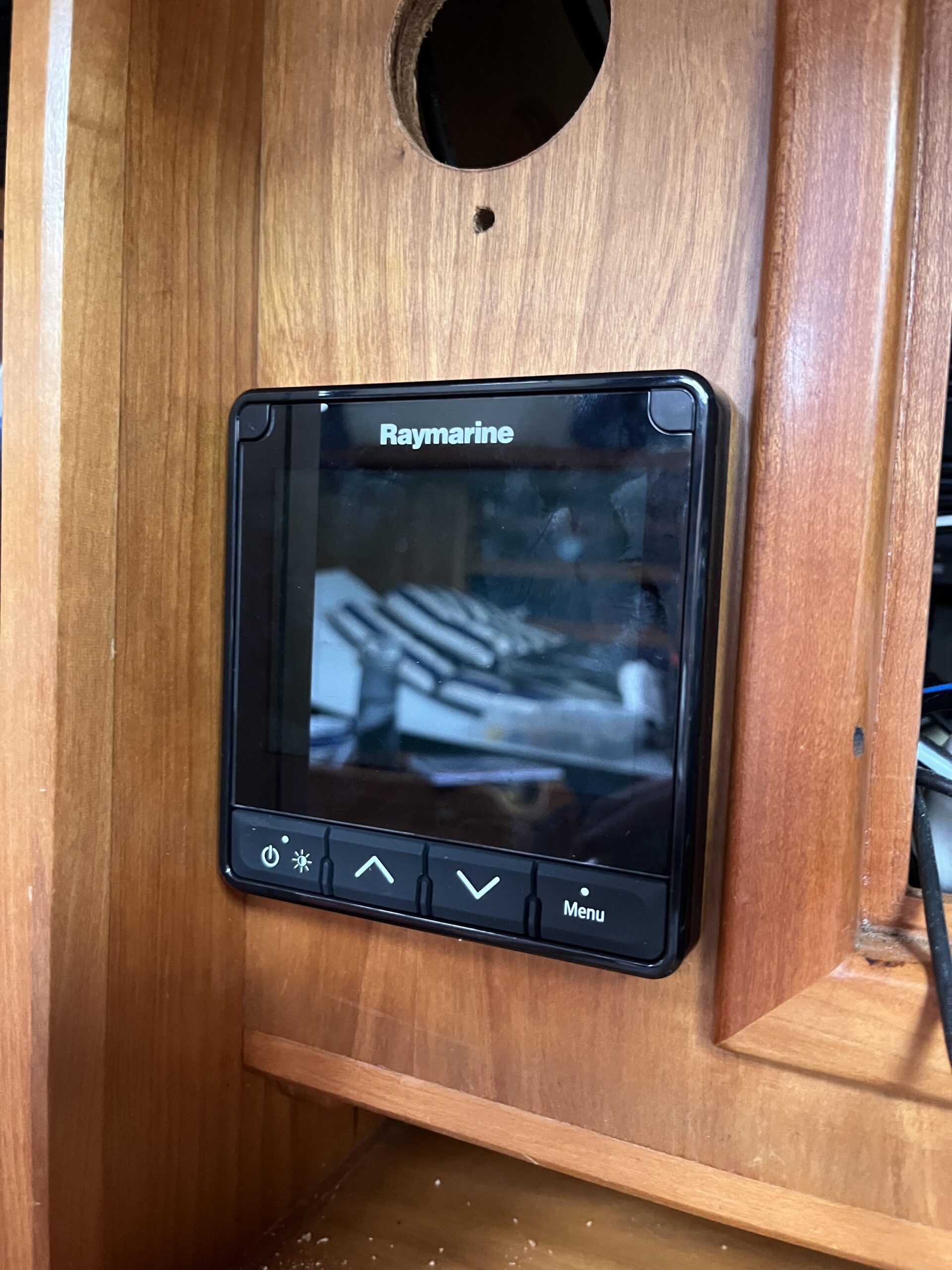
So yes, while the result looks a bit like woodworm, the i70s now fits nicely. I can always unscrew it and apply an actual chisel to clean up the holes. Speaking of holes, it turns out the screws used for mounting the unit are a bit smaller than 3 mm, but I’d only drilled two pilot holes at that point. One of them was a little un-grabby on the threads, but then I noticed I didn’t have the unit quite plumb. Fixed that and all 4 holes and screws are holding nicely.
Next up was screwing the false wall back on under the heads sink, tidying up the ACU wiring a little bit, installing the ground connection to the negative power terminal, mounting it in place, and putting on the cover on.
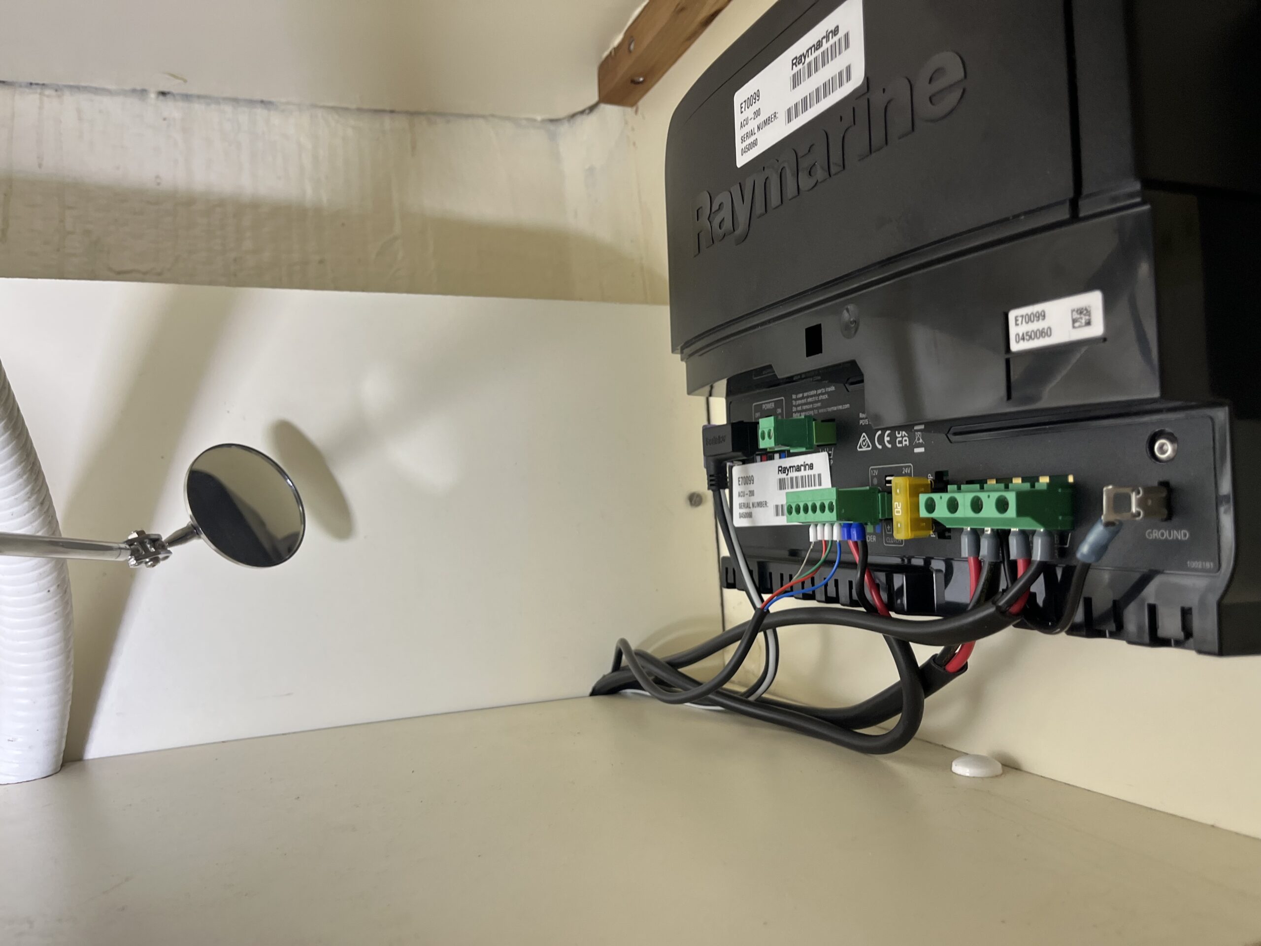
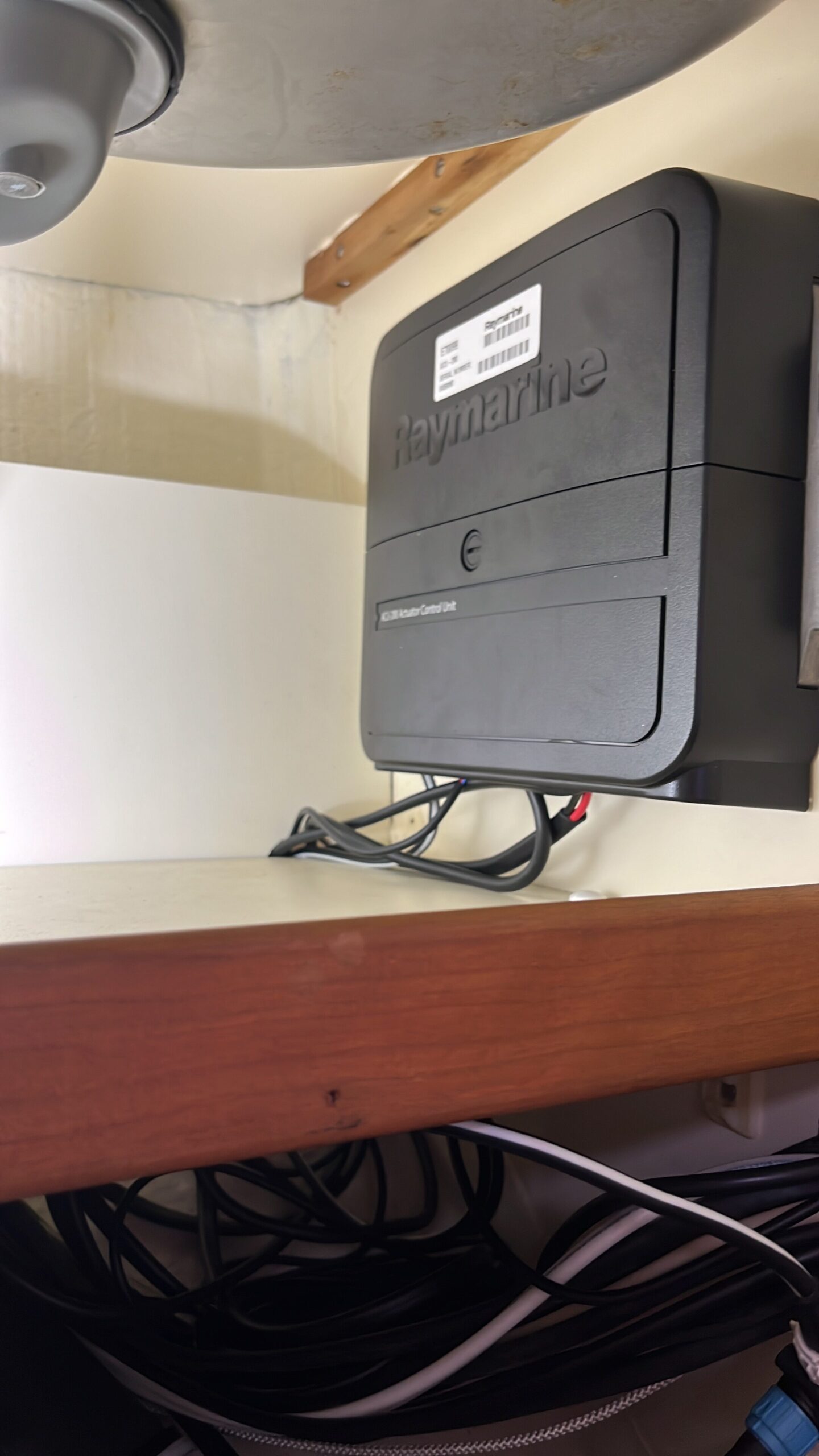
Not much else to say about that bit of work – just need to put the locker door back on sometime before launching.
The final bit of work for the day, before tidying up, was to connect the ITC-5 to the transducers. This is when I re-discovered that Raymarine are tight-fisted and only ship 10 mini spade crimp connectors with the ITC-5, but the unit has 22 terminal connectors.
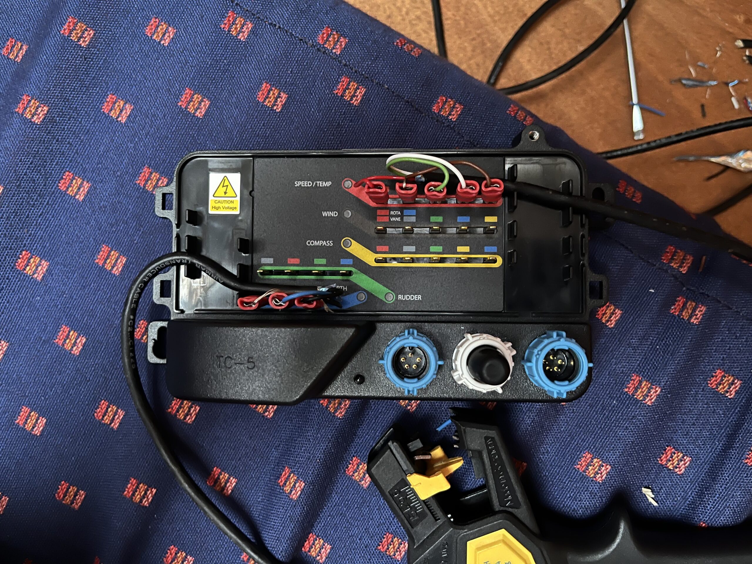
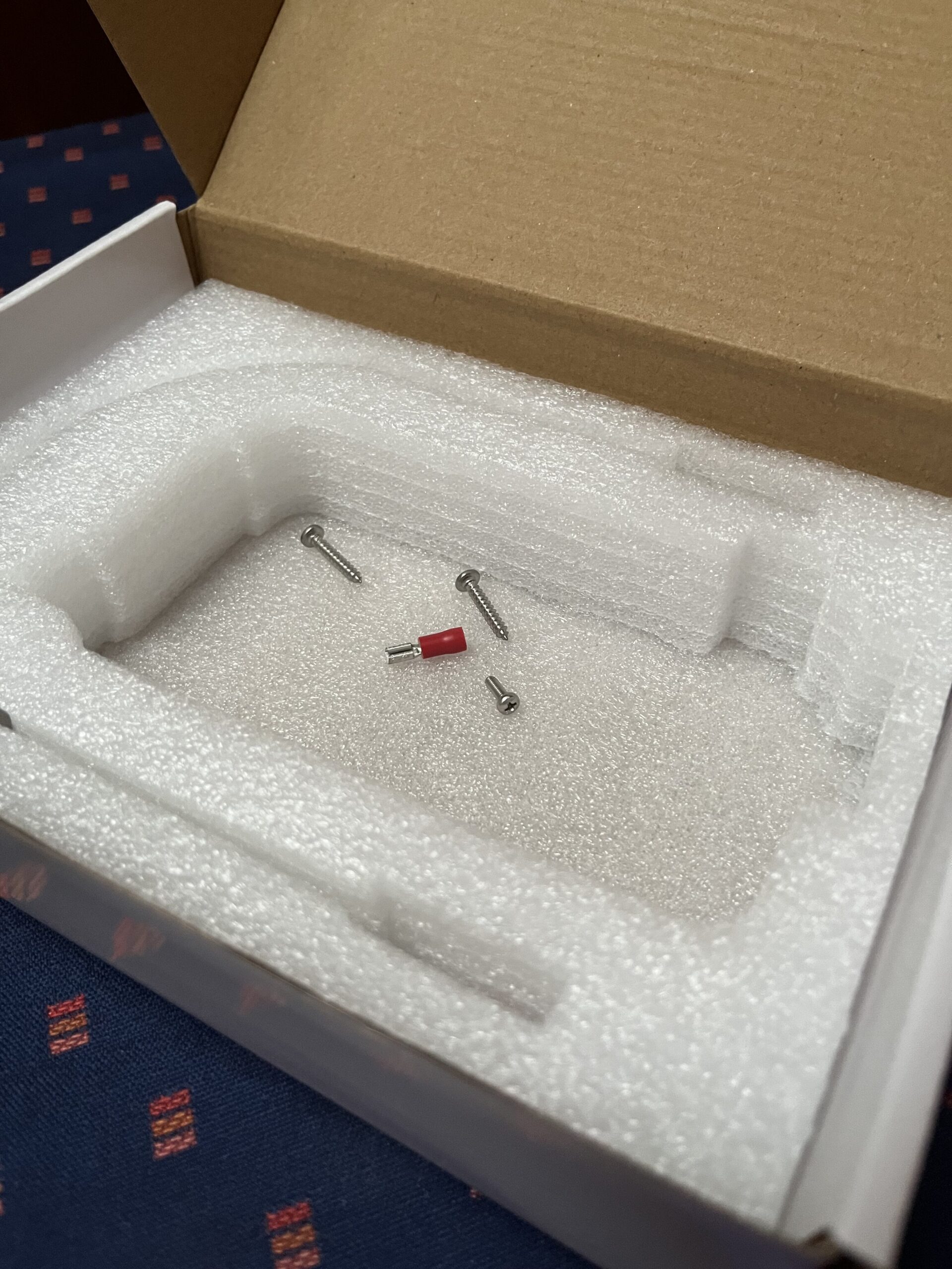
So I’ve had to order a packet of 100 mini spade (2.8mm) connectors just to get 3 of them. I have no idea what I’ll use the other 97 for. I think Raymarine have earned themselves a complaint for that one.
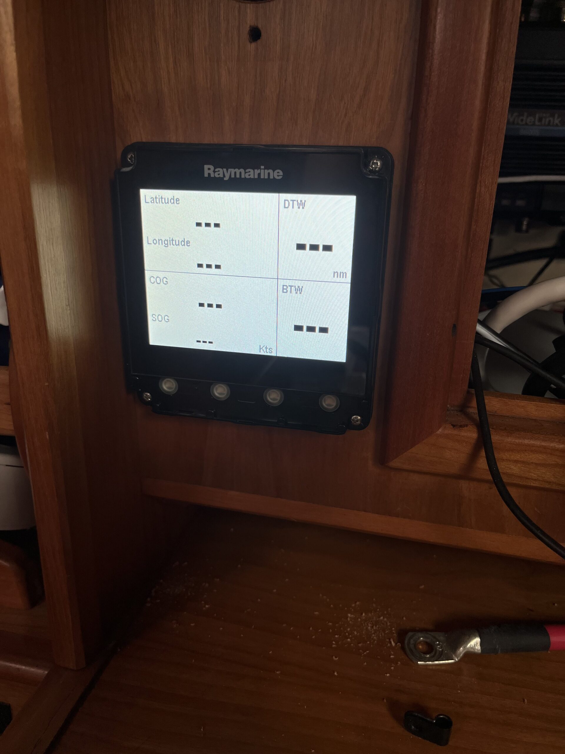
However, with everything (almost – I need to route the wind transducer to the ITC-5) connected, I booted the network again and the i70s at the chart table could see the ITC-5. Depth was “–“, which makes sense at the moment – there’s no water in the way, and temperature was way off. Both will be sorted once there’s water over the transducers, and then I can calibrate the speed. Of course, once calibrated, a crab will move in.
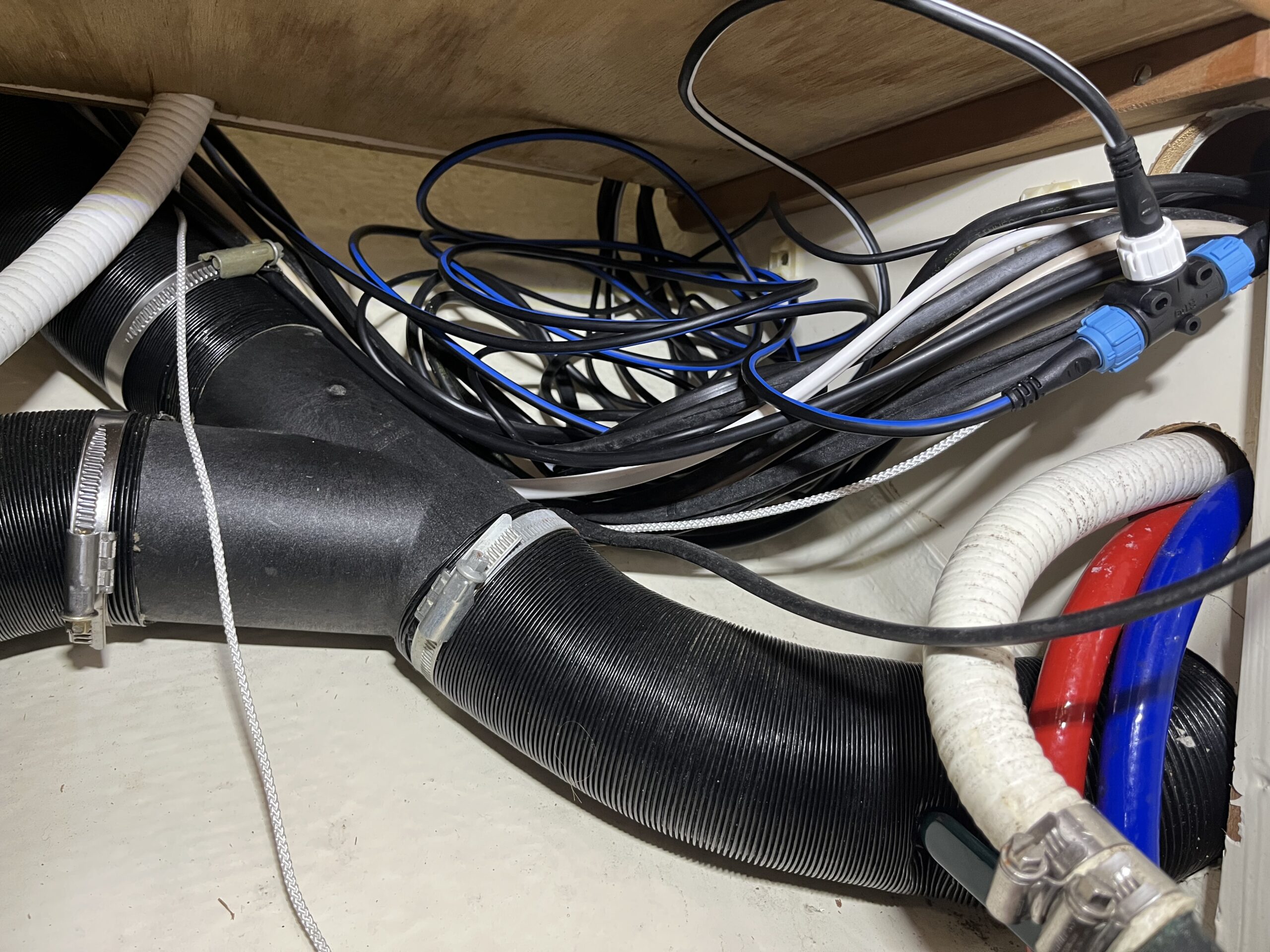
With the work done, I pulled everything out from the port side of the saloon so I could get the wind transducer cabling freed up into the water pump area (where it comes in from the mast), and then tidied the boat away. She’s been a mess for the last month+ as works have happened, but I’m into the closing up stages. It’s taken far too long because I’ve done the work myself on weekends with K’s help – but I’ve learned things about the boat, understood the construction, found and solved problems, and have better knowledge about where things are.
The works remaining are
- Get the wind transducer cable over to the ITC-5
- Mount the ITC-5
- Tidy the cabling for the ITC-5 (I didn’t shorten any of the transducer cables)
- Sort power for everything in the wiring locker (data bus power is a flying lead at the moment)
- Linear drive base plate move (yard)
- Sound insulation (yard)
- Diesel tanks back in and connected (yard)
- Engine mounts (yard)
- Engine installation and alignment (yard)
- Anchor shackle and load the anchor on the roller
- Anti-foul
- Tidy the boat
- Splash