Saturday
The list of works for Saturday was essentially “make progress to not being in the way of the engine re-installation”.
- Install nyloc nuts on the linear drive
- Connect the linear drive to the rudder arm
- Install the rudder reference sensor
- Connect the reference sensor to the rudder arm
- Pull the cable for the reference sensor to the ACU
- Pull power and clutch cables from the linear drive to the ACU
- Connect the power and clutch cables to the linear drive
- Remove the trunking from the underside of the cockpit sole
- Re-arrange power/data cabling ready for sound insulation installation (p-clips and long screws)
- Get the old anchor off so it can go in the garden
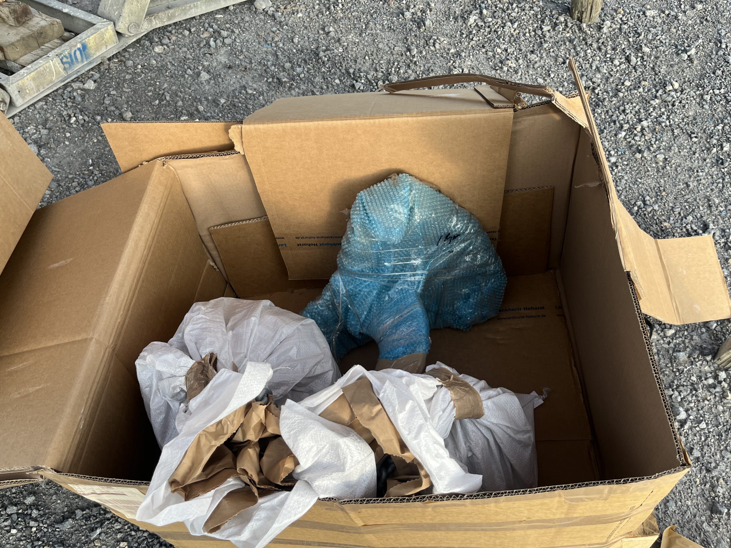
- Get the new anchor, chain, rode on board
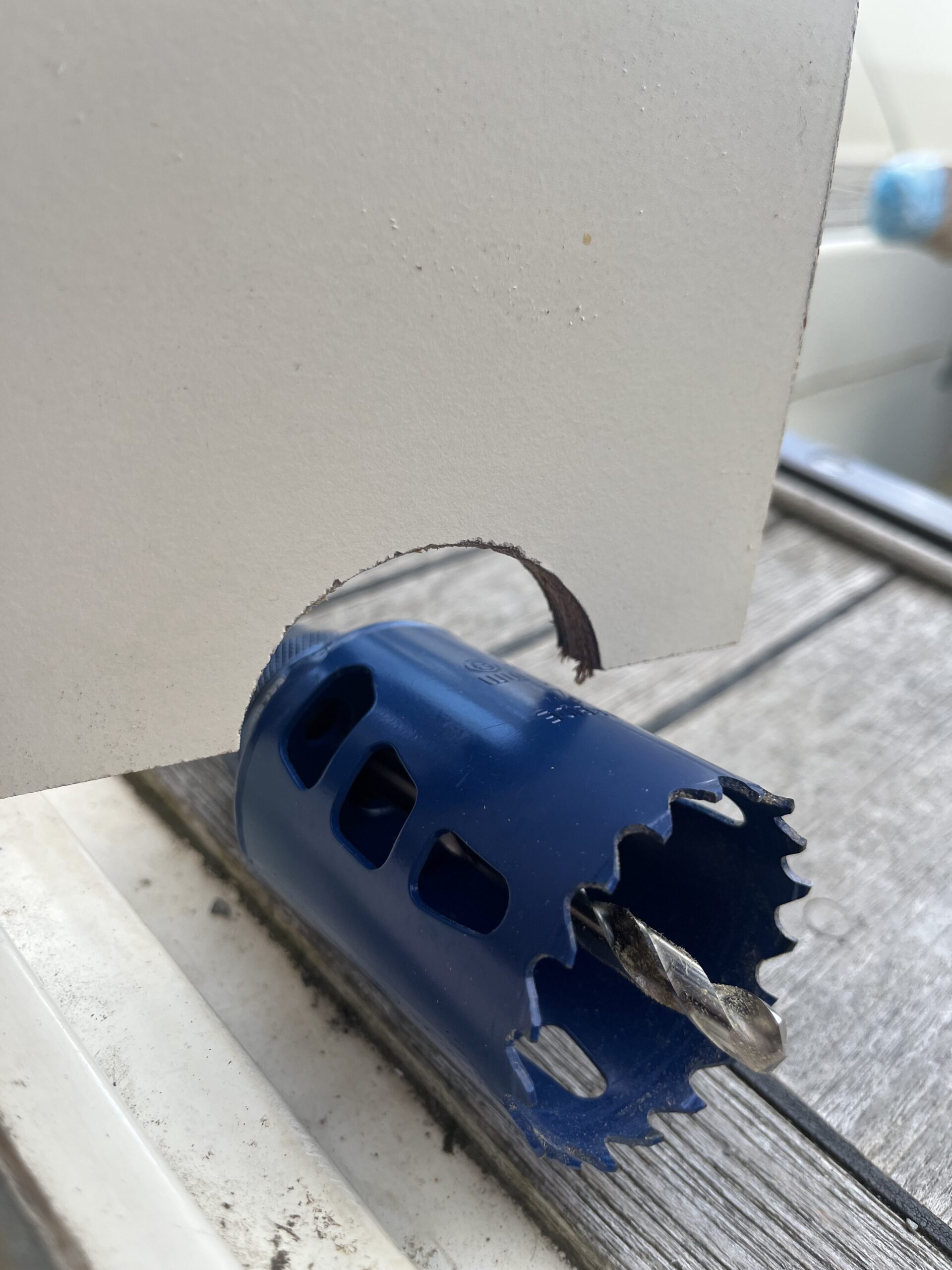
We visited Screwfix on the way to get some hole saws – a 51mm and 92mm. Didn’t use them today, but I’ve confirm that they’re the right size for the work, and thus don’t need returning.
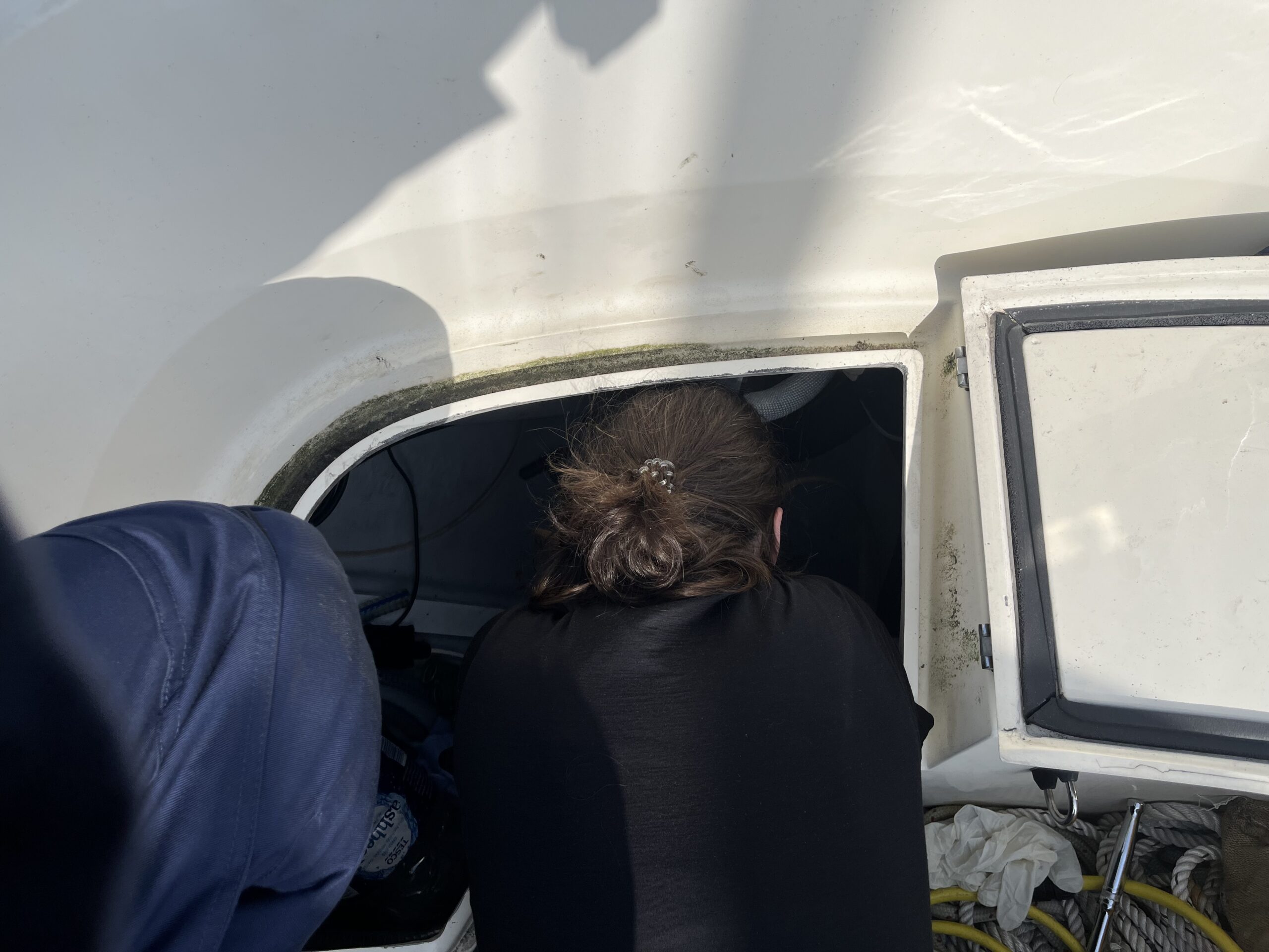
Far fewer photos from the last few posts, as there was a lot of work in cramped spaces with not much to show for it. However, the listed works are done. The first job was getting the nylocs on, now that we had full access to the heads of the bolts.
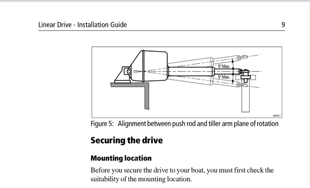
I noted previously that the yard had put in the old linear drive “upside down”, so that the rose joint on the end of the arm went over the pin from below, not above. I now know why – had it been on top, it would have been out of spec for the 5 degree restriction (no more than 5 above or below horizontal (page 9)), and it probably would have bound with the rose joint from the drag link of the Whitlock helm. The unit could have been lifted further up the bulkhead to bring it back to horizontal, but that would not have solved the binding issue.
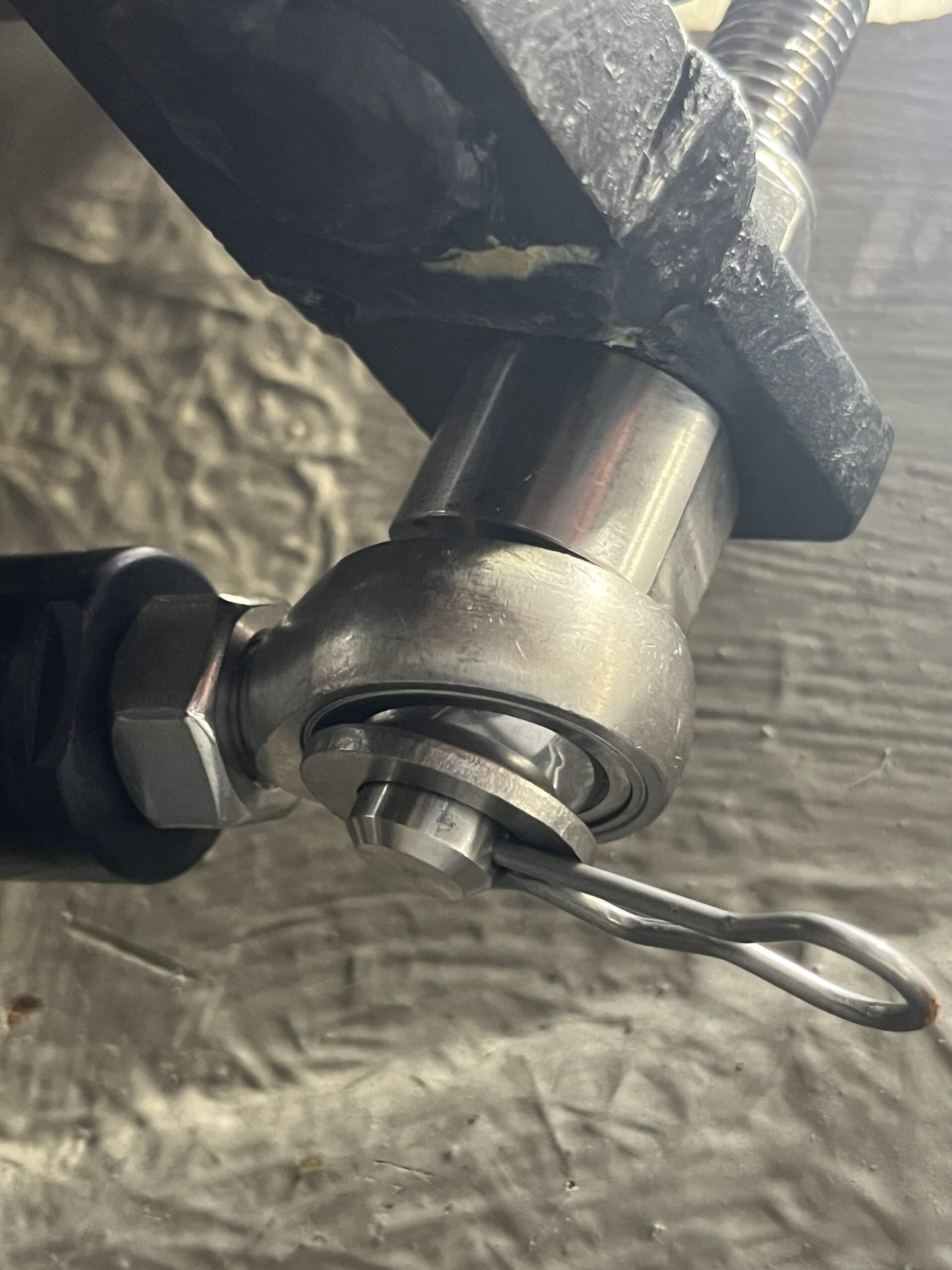
For the first attempt at getting the rod end on to the pin, and clipped into place, I tightened the lock nut up so that the pin was held securely in the rudder arm. Unfortunately, this resulted in an installation where the R-clip would go through one hole, but not pop out the other side – it was binding on the edge of the washer. After a lot of faffing, and K trying to put it together as well, we ended up with me going into the cavern (I wish it was a cavern, I’ve got the bruises to show it isn’t) to hold the rudder arm up while K tried to get the pin in. After that failed, I concluded the problem was the bushing of the linear drive rod end was angling down sufficiently to block any attempt at installing the R-clip.
So, the final solution was to back the lock nut all the way off, assemble the rod end rose joint onto the pin, install the washer and R-clip, and then hold the assembly in place and K ratcheted the lock nut back on. Simple once you work it out, and had we done it that way from the start, it would have been about 5 minutes instead of over half an hour.
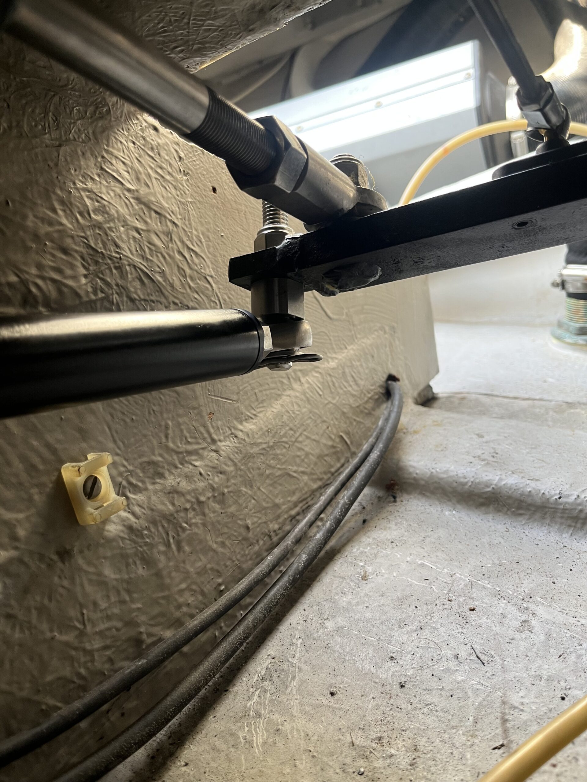
For the rudder reference, it turns out the yard that built Blue Opal hadn’t bothered to cut the threaded rod, and Raymarine haven’t changed the length of the rod either. This meant that the existing holes for mounting the reference unit are in the right place, and it was a simple matter of bringing the rudder to amidships, screwing the rudder arm end piece in place (previously bolted, but the screws seemed to work just fine), clipping the threaded bolt into place, and then getting the two slightly visible marks on the base unit and the swinging arm to line up so that the first screw could be tightened to hold it all in place.
It looks like the run of the SeaTalk ng backbone from helm to ACU is more than 5 metres – the cable stops short 2/3 of the way along from the back bulkhead of the heads to the bulkhead of the sink assembly. I might just cut and splice the 20 metre cable (though perhaps I could try flogging it instead) or I might order an extra 1 or 3 metre backbone cable from SVB in Germany, and a backbone joining connector. The rudder reference has enough length on it (I think it’s a 7 or 10 metre cable) to reach the ACU, and the power cables have been laid in too (though not connected to the ACU – ran out of time).
For the main power feed from the ACU to the linear drive, I’ve opted for 4mm2 cable, and for the clutch I’ve used 2.5mm2 (since that’s what I’ve got). According to the installation manual, the 2.5 would probably have been enough for the main power feed, but at a potential 20 amps of pull, having some more copper doesn’t hurt. The 4mm2 has been terminated with Power Pole connectors, and the 2.5mm2 has been terminated with standard spade and spade-receiving. As with the tank sender, I’ve set up the clutch cabling with one spade and one spade receiver on each side, so the polarity can never be reversed.
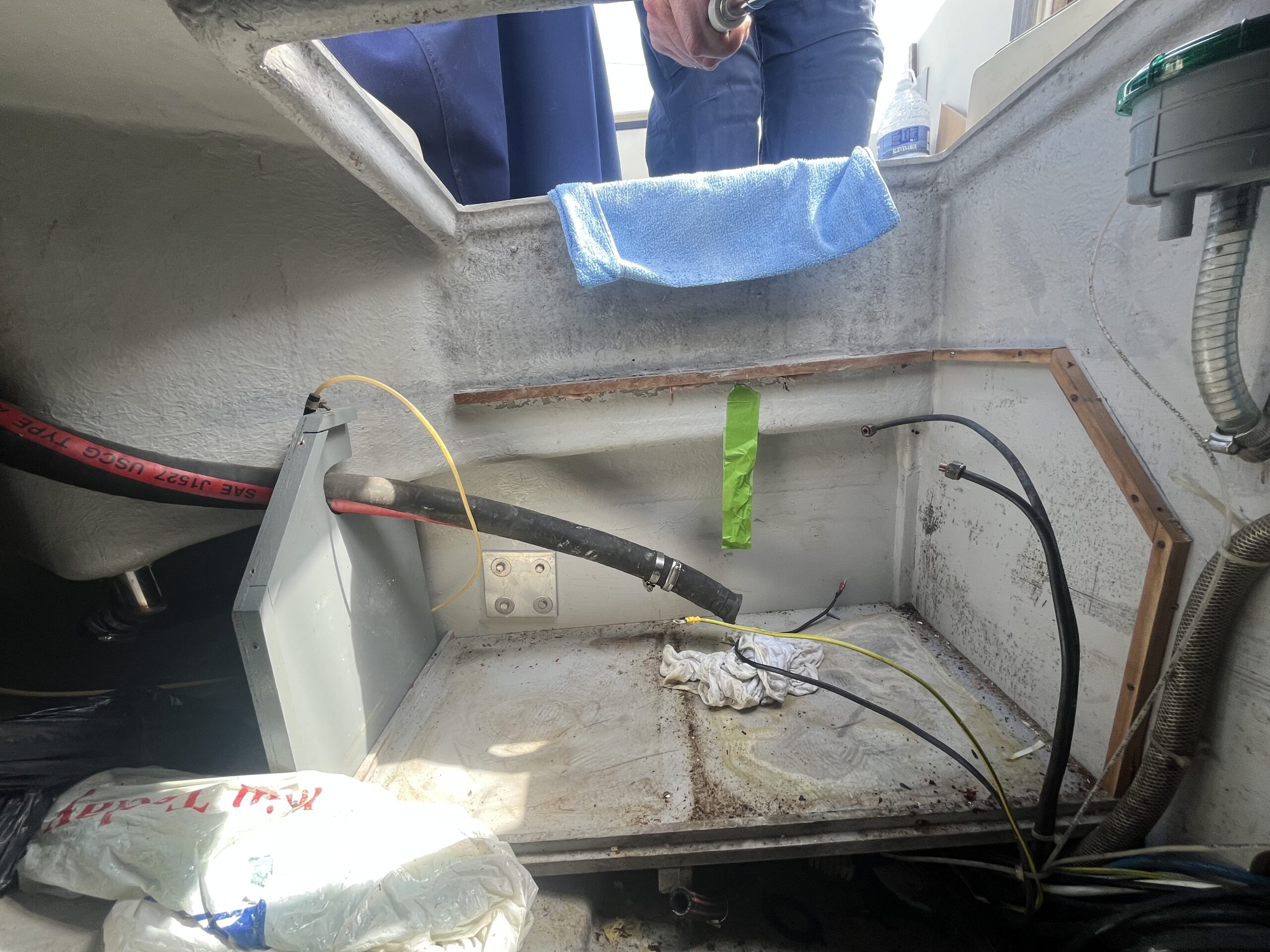
All of the wiring has been re-sorted, the trunking has been removed, and the various parts of the under-sole area marked up for where sound insulation should/could be installed. The yard has my approval to purchase the insulation (it’s not cheap at ~100 EUR/panel), and that should get installed soon.
At this point, the diesel tanks can be reinstalled, the sound insulation can be installed, the engine can go back in, and maybe I’ll add a flexible coupling between the gearbox and the shaft end. Waiting for the yard to confirm whether there’s space to fit it.
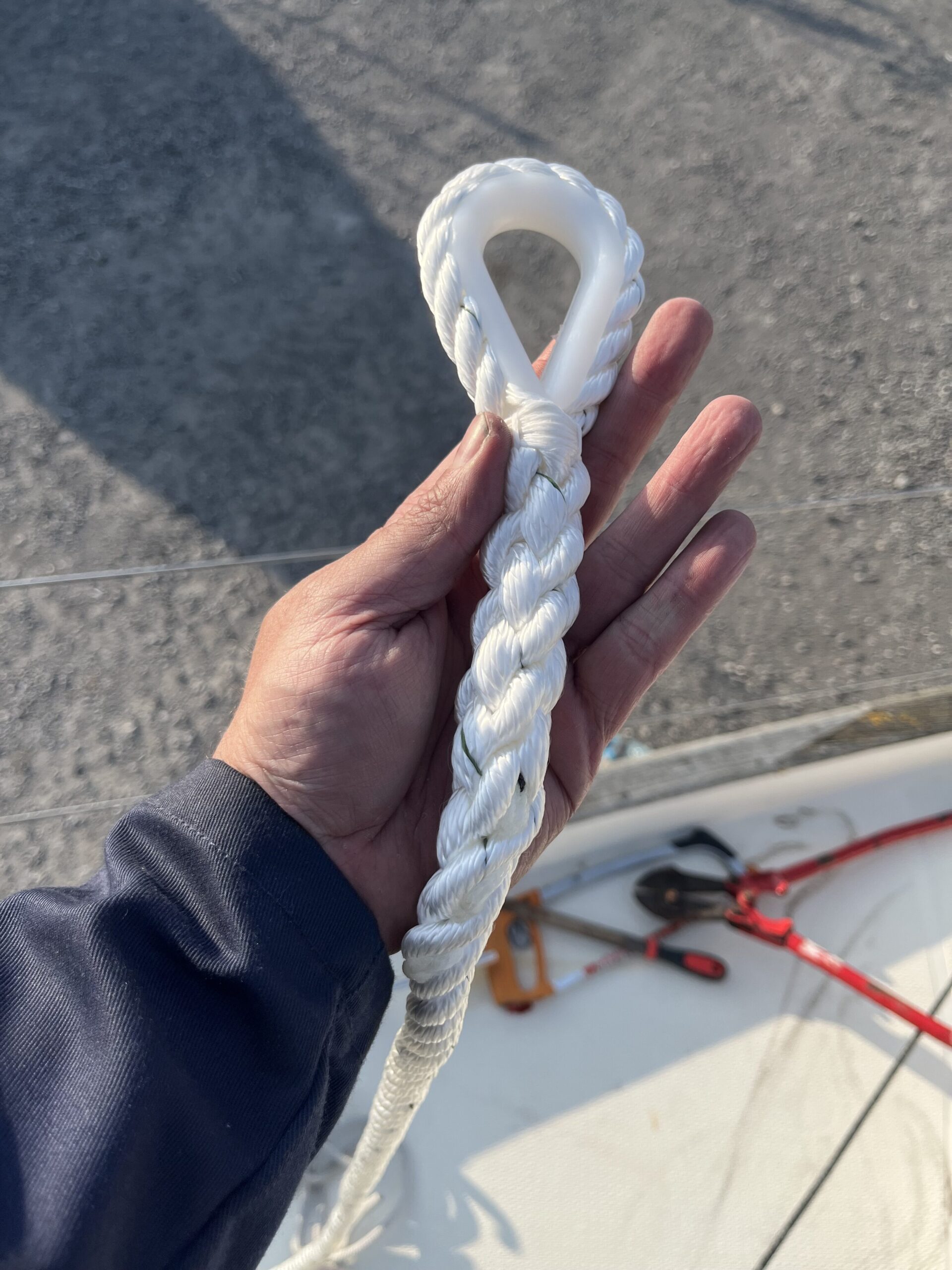
Finally, the new anchor, chain, and rode have been pulled up on board, and the old CQR has been consigned to the garden. I attempted to cut the 8mm chain of the old anchor with a hacksaw, and someone wandered over and offered me a set of bolt cutters that were going in the bin. Two snips and the chain was cut ever so neatly. Now I just need two shackles for the chain to anchor connection, and to run the chain up from the locker and over the windlass chainwheel, and the anchor will be in place for the launch.
My bruises have bruises.
Sunday
With agreement from K, we went back to Blue Opal on Sunday – Saturday had run longer than intended, and we didn’t get home until 10 pm.
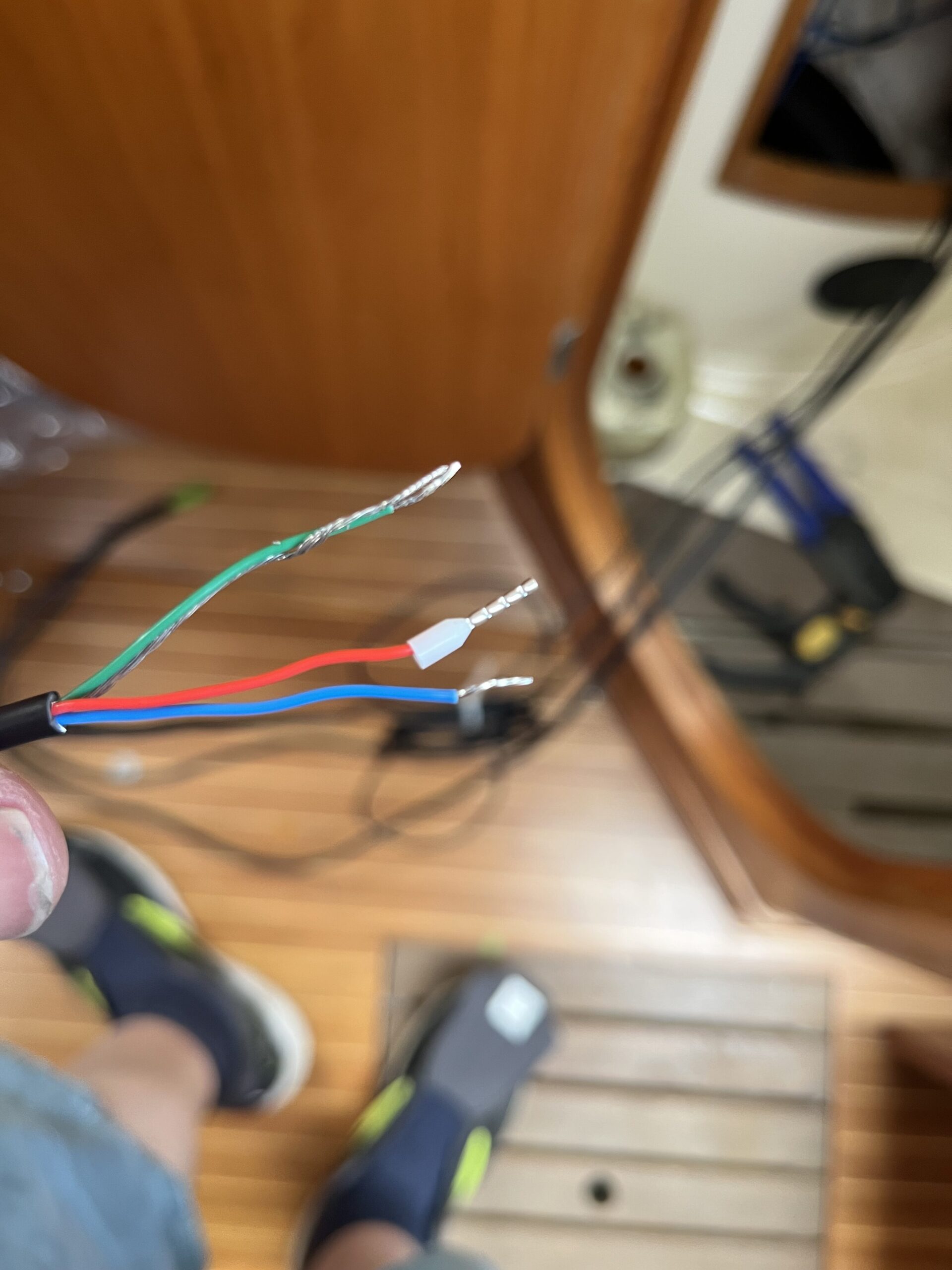
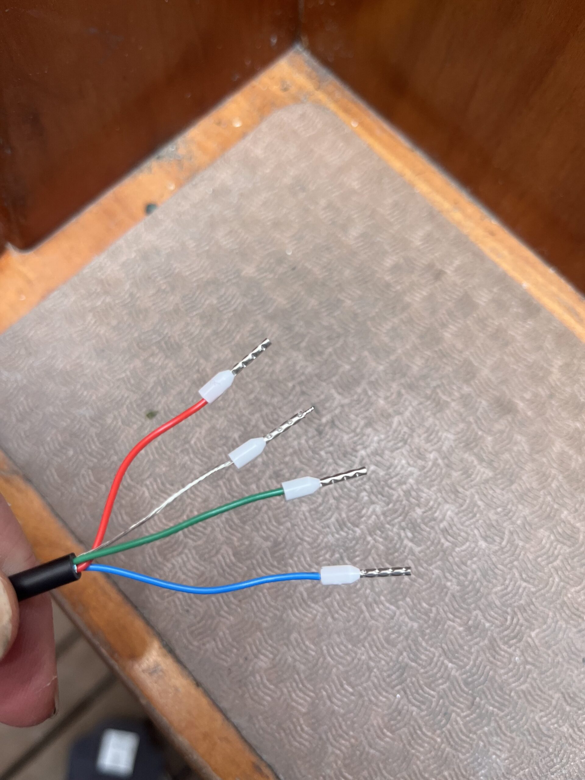
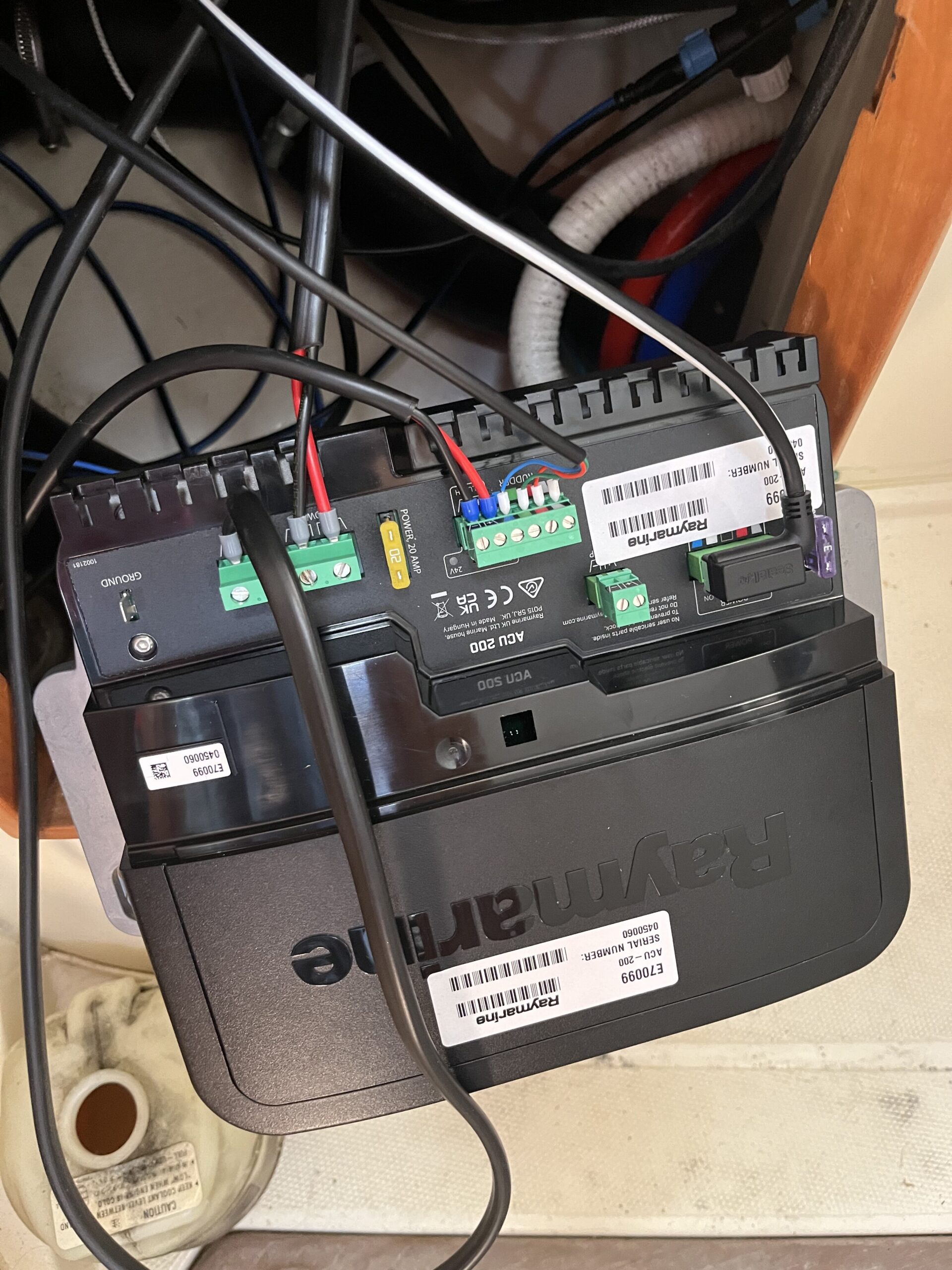
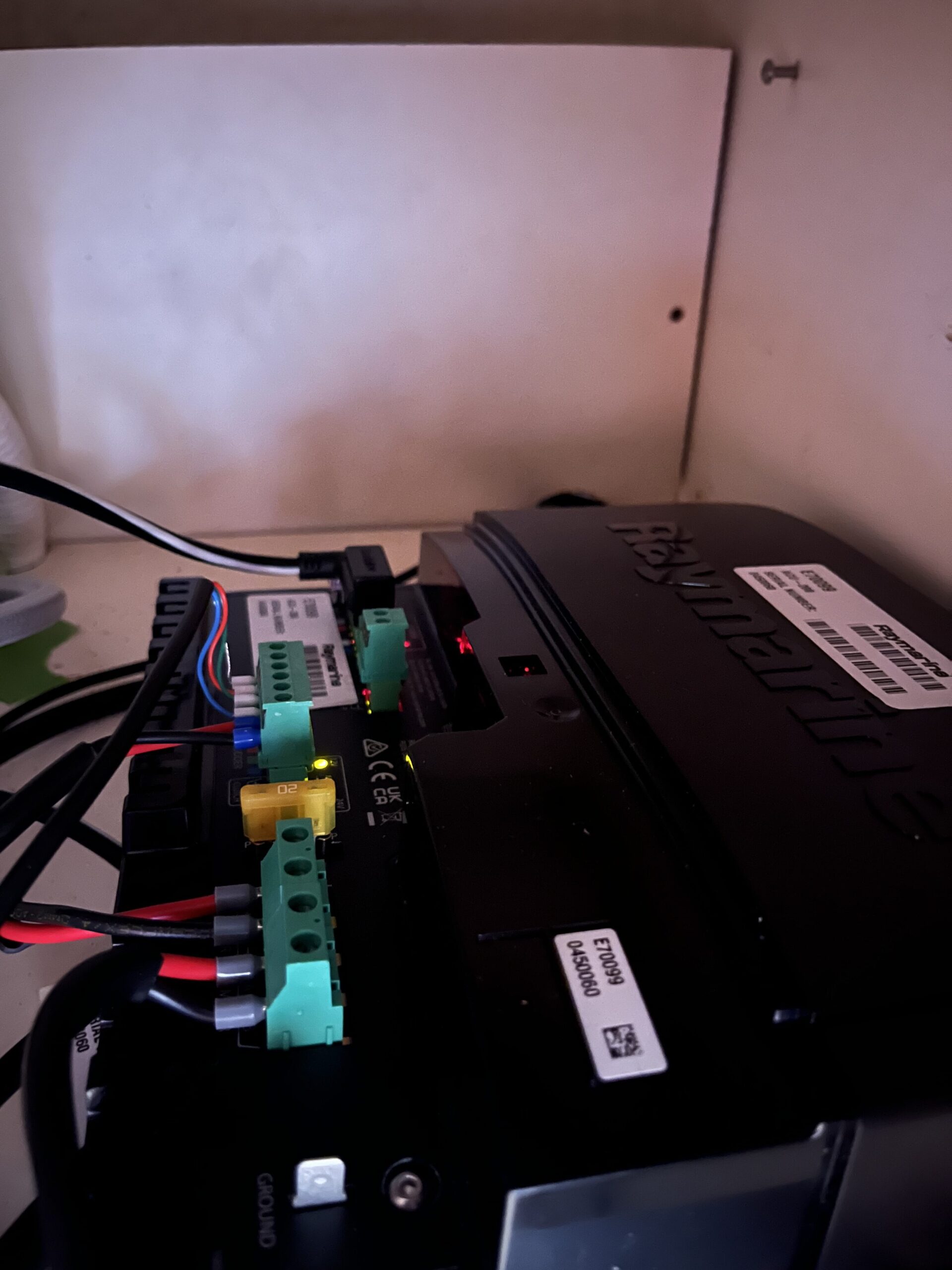
The goal for Sunday was to get the ACU, linear drive, EV-1 compass, and p70s head all talking to each other – whether that meant power or data. The first order of business was to get bootlace ferrules on all of the wires that had to go to the ACU for power or data. While the terminals on the ACU are the good type – the design where the screw moves a piece of metal up and down to clamp the wire, instead of the screw meeting the wire – I’ve formed a preference of using the bootlace ferrules now that I have the right tools. The red/blue/yellow crimp-on pins would also work, but I find the crimp on the bootlace to be far nicer. K did a bunch of the crimping work, which gave me a break from doing all of it.
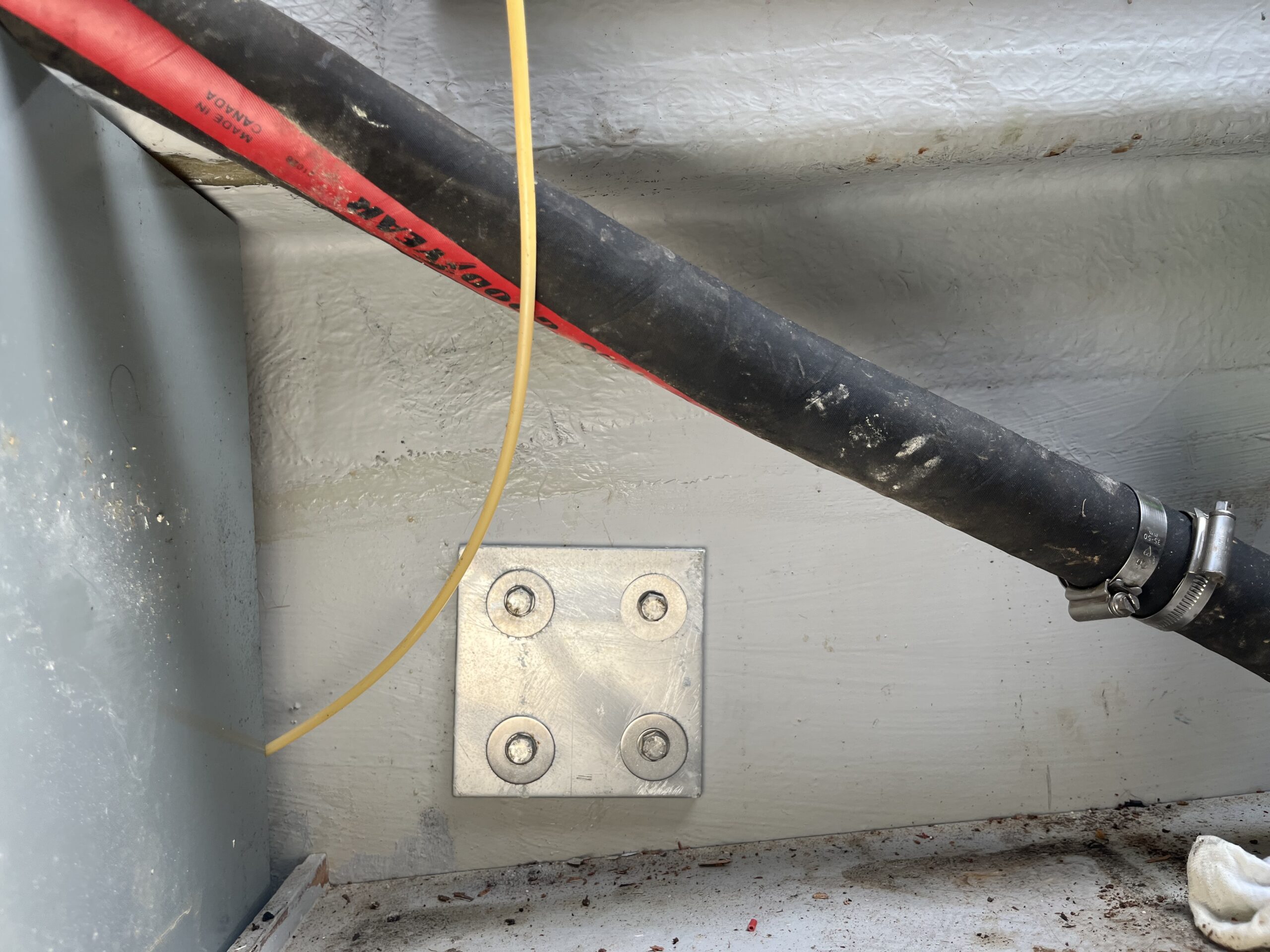
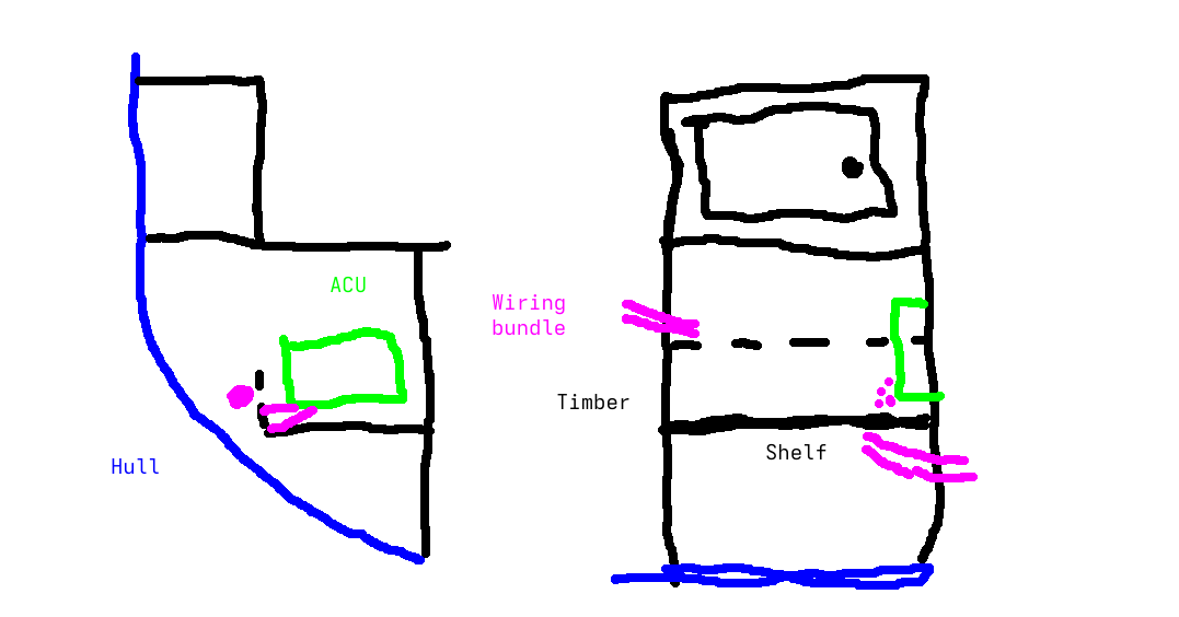
The 2.5mm2 and 4mm2 power cables for the main power and clutch power received the same type of ferrule, and everything connected nicely to the ACU. To cleanly route the cabling to the ACU, I opted to use the 51mm hole saw and a bit of MDF I had in my bag (brought to do this kind of thing) to cut an opening in the bottom of the back of the shelf. The paint diagram in the next gallery probably makes this as clear as mud, but there’s a shelf under the sink in the heads, and there’s a “false wall” at the back of it to stop things sliding off and to hide all the cabling running from the chart table to the rear of the boat.
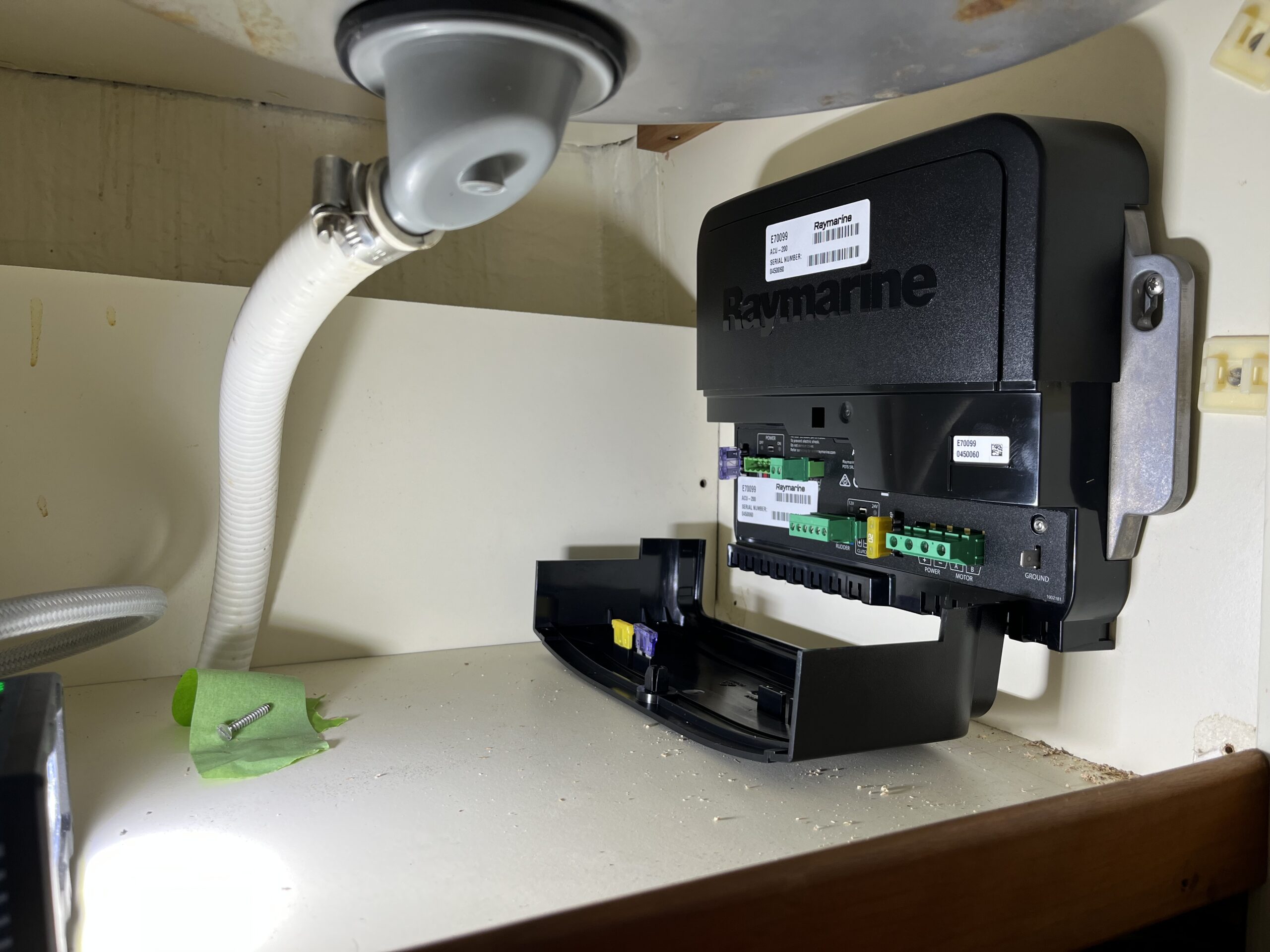
It turns out there’s just enough slack in the backbone cable for it to pop out the hole under the ACU, where all the cables going sternwards are located. The ACU’s custom SeaTalk ng to breakout cable is long enough to reach a T-junction that joins the backbone from under the ACU to the 5-way connector that’ll be in the wiring locker behind the chart table. Means I can return a bit of backbone cabling to SVB, as I won’t need it to make that run. And, if the backbone cable needs to pull backwards a bit, there’s still enough length in the ACU cable to reach – I’d just have to run it towards the locker door instead of out to the hull and back around under the shelf.
The next adventure was to get the EV-1 compass installed behind the chart table drawers. This took a bit longer than I thought it would, mostly because the templates for the EV-1 installation just show how to mount the bottom bit (it comes in 4 pieces) on a vertical surface, or the top bits on a horizontal surface. In my case, I needed to somehow combine the horizontal surface template with the vertical surface template to get an overall width. Even then, I didn’t have the overall height, and as the photo shows, there’s a drawer that runs right over the top. In the end though, I’ve got a few mm of clearance to the side and above, and the drawers fit.
A bit of vacuuming, a takeaway chicken and chips from Macari’s eaten in the car while we watched the sun set on the marina, and we were home by 10 pm. Midsummer is such a strange time.
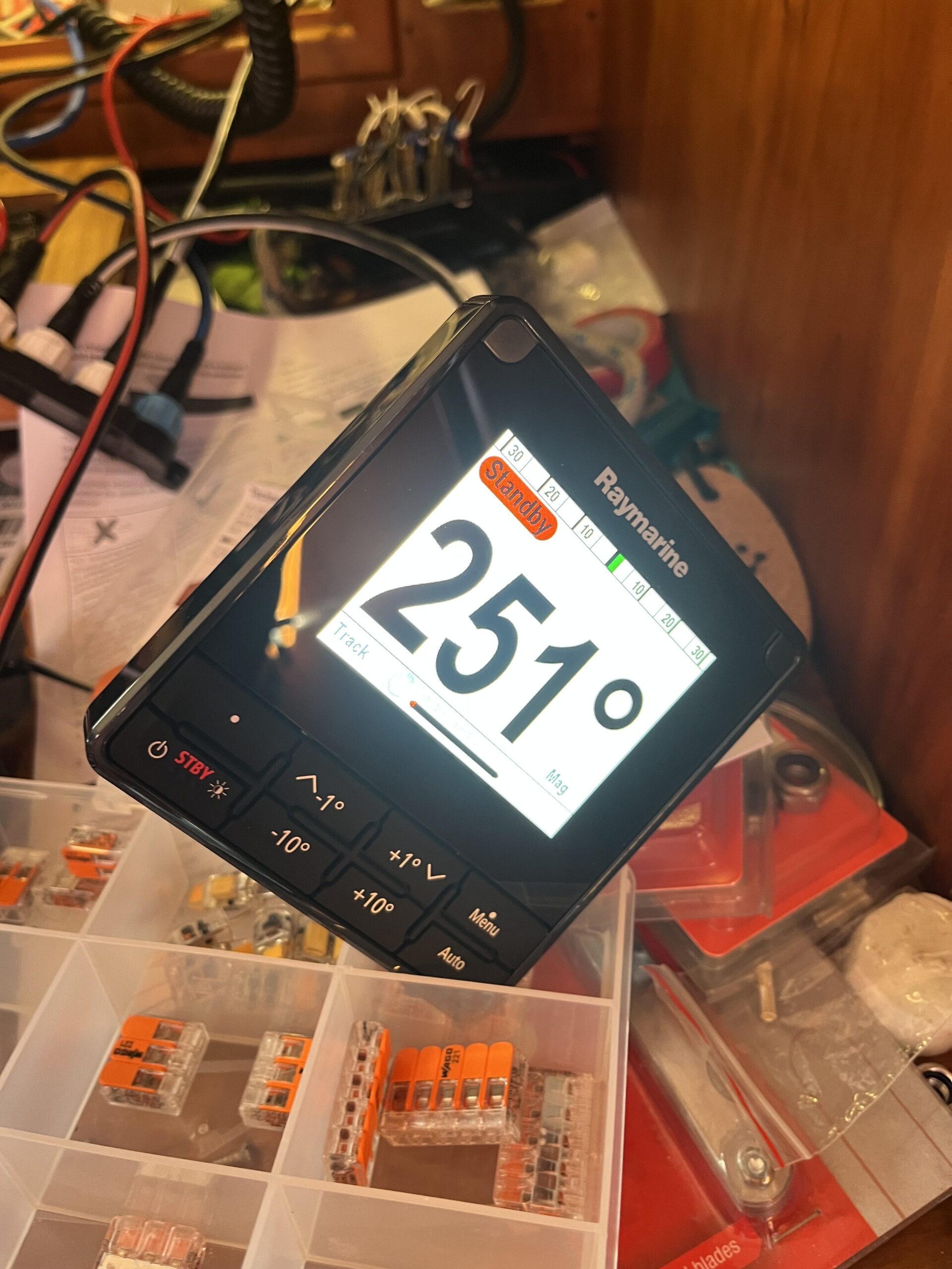
I’ll have to go back and run the calibration to make sure I can swing the rudder from the p70s. If it works, then the engine can go back in.