I spent part of Friday, and most of Saturday working on getting the AIS unit integrated into Blue Opal’s network, measuring the output of the engine tachometer, and generally fiddling with the electrical wiring locker (tidying it mostly). The end result is that the locker is tidier, the B600s is mounted properly in the locker, wires have been clipped to various bulkheads with some P-clips, labels are now applied to various fuses and cables, and I have some saved waveforms from the tachometer. I also have a list of parts to buy and other maintenance to do.
I started out on Friday with the goal of gettting the AIS plugged in and talking to the ShipModul MiniPlex 3. To get to that stage though, I needed to re-organise some of the wiring in the wiring locker, build (cut, strip, crimp) some new power leads, charge the battery, run the engine out of fuel by forgetting to open the diesel fuel valve, spend an hour+ bleeding the fuel lines to get the engine to start, and otherwise rediscover a fuel leak that I knew existed, but hadn’t isolated.
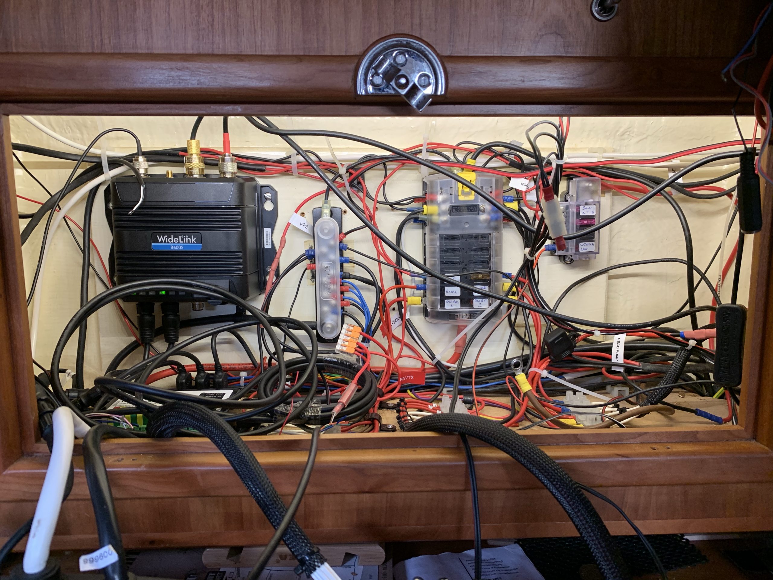
I’ve said it before, and I’ll say it again – that wiring locker is in about the most frustrating place for me. It’s just that little bit too far to the hull-mounted wooden panel from the seat at the chart table, so while you can turn a screwdriver and undo a screw in a busbar, you can’t actually reach the wires. The best approach I’ve found so far is to kneel on the starboard berth, facing aft, and stick my head and shoulders over the chart table. Not the most comfortable position to maintain.
To get the B600s wired in to the instruments switch on the first switch bank, I decided against trying to get 3 wires into one side of a small screw terminal (chocolate block), and opted instead to cut some wire so that I could use a Wago 221 connector (the orange thing by the thin bus bar in the middle of the picture). For those who don’t know them, they’re like a screw terminal, but with spring-loaded clips, and they’re rated for 240V household wiring, so 12V low amp stuff is well within their capabilities. All wires on the connector are connected by a tiny bus bar at the back.
Getting the B600s mounted on the wooden panel required me to move a few of the zip-tie attachments; there’s pretty much only one place the AIS unit will fit right now, until I decide to move everything around (so the big Blue Sea fuse block to the far right of the board, and bring the mini fuse block left, and above the negative bus bar (which would move right as well). However, it all works right now, and with labels, it’s not too hard to tell what wire is for what (and hopefully I’m never having to be in this locker in an emergency).
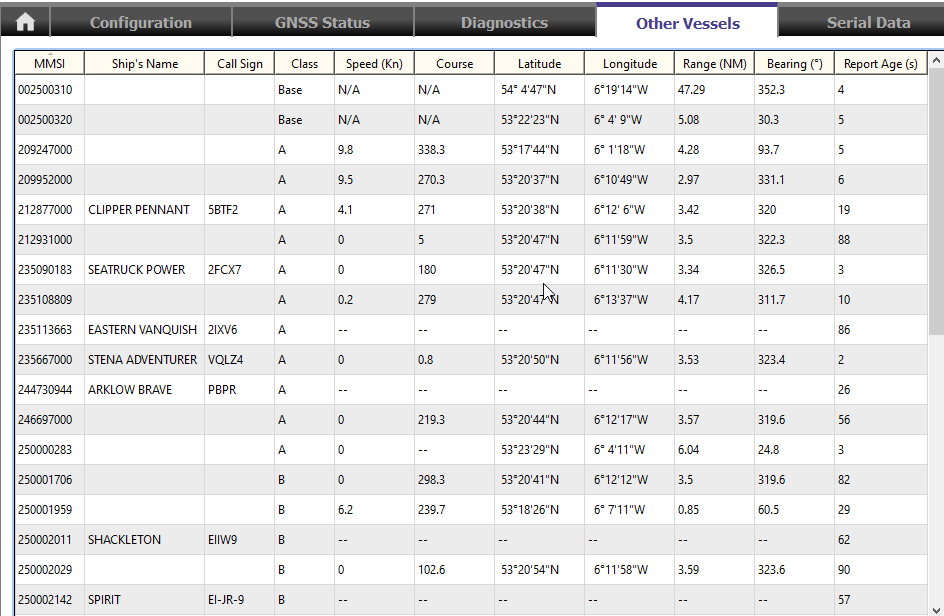
The B600s seeing nearby vessels, ATONs etc 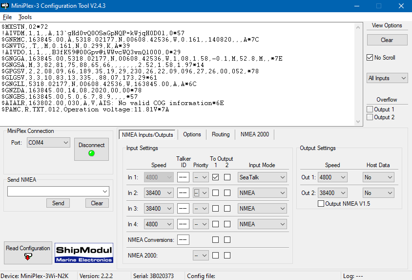
It speaks!
So yes, the diesel thing. I had the MiniPlex software running, so that I could monitor the output to make sure I’d wired things correctly. I hadn’t done so initially, and had even resorted to using the oscilloscope (a HDS1021M-N by Owon) to make sure the unit was putting out signal voltage. NMEA 0183 is RS-422 under the hood as best I know, and there was a very clear digital signal in the voltage being put out. A back and forth with Dad as I was re-reading the documentation showed that I had connected Transmit + and Receive -; that definitely won’t work!
You can see what caused me to turn the engine on in the screenshot above – “Operation voltage: 11.81V”. At the time, I attributed this to the MiniPlex, but as I write this blog post I see it was the B600s that was the source of the message. Either way, I hurried to turn the engine on thinking my battery was in a bad state (the battery voltage monitors I installed last year were unplugged to stop them drawing power), opened the seacock, turned on the engine battery switch, set the throttle, and started the engine. I completely forgot to open the diesel fuel valve in the cockpit locker. At this point, Padraig was passing by in the launch, and as we’re chatting I heard the dreaded sound of a diesel engine winding itself down without the throttle being touched.
I knew I had at least half a tank of diesel, so even though I got the fuel valve open before the engine stopped, I was too late – air block in the line. An hour and three bleeds later, I got the engine running smoothly, but it wasn’t without difficulty. The access to the lift pump, primary fuel filter, and injection pump is all done via a tiny hatch in the heads. You can prop against the head, but you can’t sit on it and still access the vital bits. Anyway, it also turned out that I cracked the wrong plugs while bleeding the engine, but no harm no foul there – they still bled the fuel line.
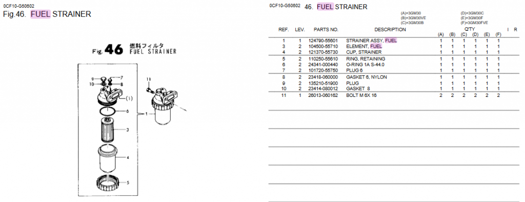
However, it turns out that I have an issue with the primary fuel filter. I’ve suspected a leak in that area for a while, and finally got proof of it. It’s not been this bad before (i.e., I’ve never seen the bubbling), so the improper loosening and tightening of this plug has probably made it worse.
According to the manual, that should be a size 8 copper washer, and I’ve acquired one from the club’s collection of copper washers; something to change today (and have to bleed the darn thing again probably) and see if the problem goes away. That screw is tightened down completely, so the washer is probably mangled in some way.
Before all of this happened, I also managed to get some readings off of the tachometer with the oscilloscope, and while my previous post on the subject said that the frequency changed, it turns out both frequency and voltage change. There’s also some nasty transient spikes in the signal.
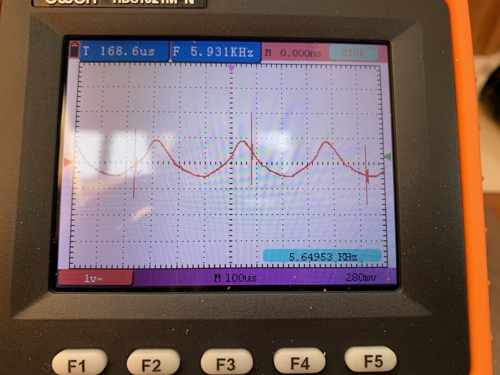
Taking a screenshot with my phone; much glare! 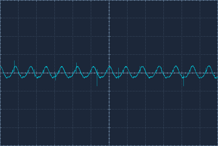
Similar waveform in the PC software
So with both frequency and voltage changing, I have options. I can feed the voltage to a ADC pin, and determine the RPM based on the relationship with the voltage, or I can feed the voltage to a digital pin, and count the pulses. To do the former, I’ll need a circuit that caps the voltage so it can’t go past ~3V (3v3 logic pins on the chip). To do the latter, I’ll need a rectifying circuit to cut out the bottom half of the sine wave, and Dad suggested a capacitor as well to capture and smooth the spikes. I can build all of this “sight unseen”, and then connect the ‘scope to the ouput before potentially sacrificing the ESP board to the gods of magic smoke.